STEERING COLUMN ASSEMBLY DISASSEMBLY
-
REMOVE NO. 2 STEERING INTERMEDIATE SHAFT
-
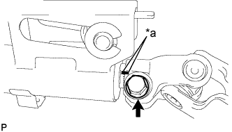
Text in Illustration *a Matchmark Put matchmarks on the steering main shaft assembly and the No. 2 steering intermediate shaft assembly.
-
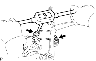
Remove the 2 bolts and the No. 2 steering intermediate shaft assembly from the steering main shaft assembly.
-
-
REMOVE STEERING COLUMN UPPER W/SWITCH BRACKET ASSEMBLY (w/o Smart Entry and Start System)
-
Using a center punch, mark the center of the 2 steering lock set bolts.
-
Using a drill, drill a hole in the 2 bolts.
-
Using a screw extractor, remove the 2 bolts and the steering column upper with switch bracket assembly.
-
-
REMOVE STEERING MAIN SHAFT ASSEMBLY (w/o Smart Entry and Start System)
-
Secure the steering column tube in a vise. Insert aluminum plates between the steering column tube and the vise to prevent damage.
Note
Do not overtighten the vise.
-
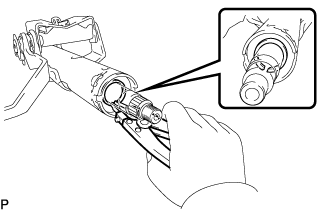
Using a snap ring expander, remove the steering main shaft shaft snap ring (outer side).
-
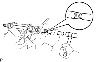
Using a brass bar and a plastic-faced hammer, remove the steering main shaft assembly and steering main shaft bearing.
Note
Be careful not to drop the steering main shaft assembly.
-
Using a snap ring expander, remove the steering main shaft shaft snap ring (inner side).
-
-
REMOVE KEY CYLINDER LIGHT ASSEMBLY (w/o Engine Immobiliser System)
-
Disengage the 2 claws and remove the key cylinder light assembly from the the steering column upper with switch bracket assembly.
-
-
REMOVE TRANSPONDER KEY COIL (w/ Engine Immobiliser System)
Tech Tips
Refer to the step "KEY CYLINDER LIGHT ASSEMBLY (w/o Engine Immobiliser System)".
-
REMOVE IGNITION SWITCH LOCK CYLINDER ASSEMBLY (w/o Smart Entry and Start System)
-
Place the ignition switch lock cylinder assembly in the ACC position.
-
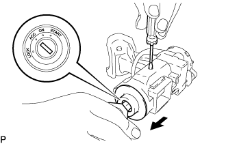
Push down the stop pin with a screwdriver, and pull out the ignition switch lock cylinder assembly.
-
-
REMOVE UNLOCK WARNING SWITCH ASSEMBLY (w/o Smart Entry and Start System)
-
for Manual transmission:
-
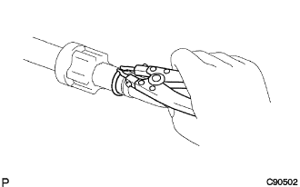
Cut the clamp securing the wire harness of the unlock warning switch assembly.
-
-
Separate the unlock warning switch assembly connector from the ignition or starter switch assembly.
-
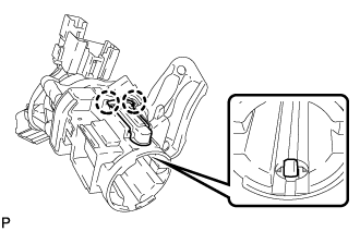
Remove the unlock warning switch assembly by pushing up on the center part and disengaging the 2 claws.
-
for Automatic transmission:
-
Remove the 2 screws and the key interlock solenoid from the steering column upper with switch bracket assembly.
-
Release the lock inside the connector, pull the terminals out, and remove the key interlock solenoid.
-
-
-
REMOVE IGNITION OR STARTER SWITCH ASSEMBLY (w/o Smart Entry and Start System)
-
Remove the 2 screws and the ignition or starter switch assembly from the steering column upper bracket assembly.
-
-
REMOVE STEERING LOCK ACTUATOR ASSEMBLY (w/ Smart Entry and Start System)
-
Using a center punch, mark the center of the 2 steering lock set bolt.
-
Using a drill, drill a hole in the bolt.
-
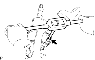
Using a screw extractor, remove the bolt and the steering lock actuator assembly.
-
-
REMOVE NO. 2 STEERING COLUMN CLAMP UPPER