FRONT BRAKE REASSEMBLY

-
INSTALL FRONT DISC
-
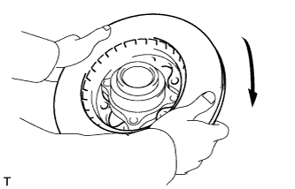
Install the front disc as shown in the illustration.
-
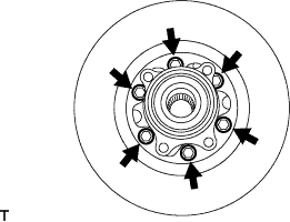
Install the front disc with the 6 bolts.
- Torque:
- 62 N*m { 632 kgf*cm, 46 ft.*lbf }
-
-
INSTALL INNER KNUCKLE GREASE RETAINER CAP (w/ Cap)
-
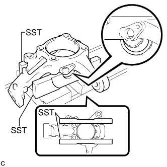
Using SST, place the steering knuckle on a press as shown in the illustration.
- SST
- 09527-30010
-
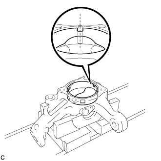
Temporarily install a new inner knuckle grease retainer cap to the steering knuckle as shown in the illustration.
Note
Align the center of the cutout in the inner knuckle grease retainer cap and the groove of the steering knuckle.
-
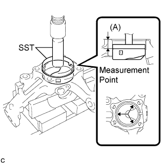
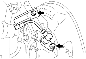
Using SST and the press, press the inner knuckle grease retainer cap into the steering knuckle until the distance (A) in the illustration meets the standard value.
- SST
- 09950-70010 ( 09951-07100 )
- 09951-00900
Distance (A) 26 +/- 0.5 mm (1.02 +/- 0.0196 in.) Note
Using a vernier caliper, measure the distance (A) at the 3 points indicated by the arrows in the illustration while pressing.
-
-
INSTALL FRONT LOWER BALL JOINT ASSEMBLY
-
Fix the steering knuckle in the vise using aluminium plates.
Note
Do not damage the steering knuckle.
-
Install the front lower ball joint assembly to the steering knuckle with the nut.
- Torque:
- 170 N*m { 1,730 kgf*cm, 125 ft.*lbf }
Note
-
Ensure that the thread and taper are free of oil etc.
-
Do not damage the lower ball joint dust boot.
-
Install a new cotter pin to the front lower ball joint assembly.
Note
Further tighten the nut up to 60° if the holes for the cotter pin are not aligned.
-
-
INSTALL STEERING KNUCKLE
-
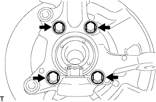
Install the steering knuckle and brake dust cover to the front axle hub sub-assembly with the 4 bolts.
- Torque:
- 88 N*m { 897 kgf*cm, 65 ft.*lbf }
-
-
INSTALL OUTER KNUCKLE GREASE RETAINER CAP (w/ Cap)
-
Using SST, install a new outer knuckle grease retainer cap.
- SST
- 09950-60010 ( 09951-00420 )
- 09950-70010 ( 09951-07150 )
-
-
INSTALL FRONT AXLE ASSEMBLY
-
Temporarily install the front axle assembly to the front suspension upper arm and front suspension lower arm.
-
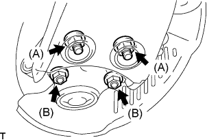
Fully tighten front suspension lower arm with the 4 bolts and 4 nuts.
- Torque:
- Nut (A)
- 90 N*m { 918 kgf*cm, 66 ft.*lbf }
- Nut (B)
- 52 N*m { 530 kgf*cm, 38 ft.*lbf }
-
Fully tighten the front suspension upper arm with the nut.
- Torque:
- 113 N*m { 1,147 kgf*cm, 83 ft.*lbf }
Note
Do not damage the lower ball joint dust boot.
-
Install a new cotter pin to the front suspension upper arm.
Note
Further tighten the castle nut up to 60° if the holes for the cotter pin are not aligned.
-
-
INSTALL TIE ROD END SUB-ASSEMBLY
-
Install the tie rod end sub-assembly to the steering knuckle with the castle nut.
- Torque:
- 50 N*m { 510 kgf*cm, 37 ft.*lbf }
Note
Do not damage the lower ball joint dust boot.
-
Install a new cotter pin to the tie rod end sub-assembly.
Note
Further tighten the castle nut up to 60° if the holes for the cotter pin are not aligned.
-
-
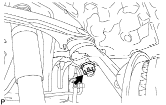
INSTALL FRONT SPEED SENSOR
-
Install the speed sensor to the steering knuckle with the 2 bolts.
- Torque:
- 8.5 N*m { 87 kgf*cm, 75 in.*lbf }
Note
-
Prevent foreign matter from adhering to the speed sensor.
-
Be careful not to damage the speed sensor.
-
Do not twist the sensor wire when installing the speed sensor.
-
-
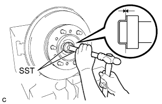
INSPECT DISC RUNOUT
-
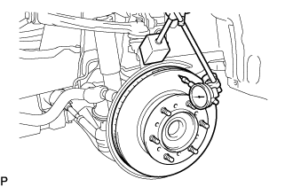
Using a dial indicator, measure the disc runout 10 mm (0.39 in.) away from the outer edge of the disc.
Maximum disc runout 0.07 mm (0.0028 in.) -
If the runout exceeds the maximum value, change the installation positions of the disc and axle so that the runout will become minimal. If the runout still exceeds the maximum, check the bearing play in the axial direction and the axle hub runout Click here. If the bearing play and the axle hub runout are normal and that the disc thickness is not within the specified range, grind the disc. If the disc thickness is less than the minimum, replace the disc.
-
-
TEMPORARILY TIGHTEN FRONT DISC BRAKE BLEEDER PLUG
-
INSTALL FRONT DISC BRAKE BLEEDER PLUG CAP
-
INSTALL PISTON SEAL
-
Apply lithium soap base glycol grease to a new piston seal.
-
Install the piston seal to the disc brake cylinder assembly.
Note
Make sure that the piston seal is securely installed.
-
-
INSTALL FRONT DISC BRAKE PISTON
-
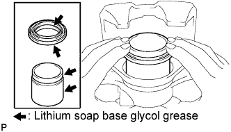
Apply lithium soap base glycol grease to the piston and a new cylinder boot.
-
Install the cylinder boot to the piston.
Note
Make sure that the cylinder boot is securely installed in the piston groove.
-
Install the piston to the disc brake cylinder assembly.
Note
Do not install the piston forcibly in the cylinder assembly.
-
-
INSTALL CYLINDER BOOT
-
Install the cylinder boot to the disc brake cylinder assembly.
Note
Make sure that the cylinder boot is securely installed in the brake cylinder groove.
-
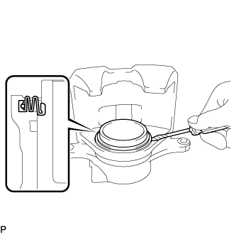
Using a screwdriver, install a new set ring.
Note
Do not damage the cylinder boot.
Tech Tips
Tape the screwdriver tip before use.
-
-
INSTALL BUSH DUST BOOT NO.1
-
Secure the cylinder mounting in a vise.
-
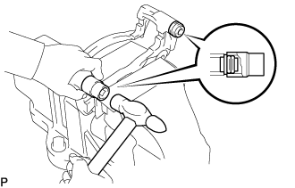
Apply lithium soap base glycol grease to the seal surface of 2 new bush dust boots.
-
Using a socket wrench (21 mm) and a hammer, install the 2 bush dust boots.
-
-
INSTALL FRONT DISC BRAKE CYLINDER MOUNTING
-
Install the cylinder mounting with the 2 bolts.
- Torque:
- 123 N*m { 1,250 kgf*cm, 91 ft.*lbf }
-
-
INSTALL FRONT DISC BRAKE CYLINDER SLIDE PIN NO.2
-
Apply lithium soap base glycol grease to the sliding part and the seal surface of the cylinder slide pin No.2.
-
Install the cylinder slide pin No.2 to the cylinder mounting.
-
-
INSTALL FRONT DISC BRAKE CYLINDER SLIDE BUSH
-
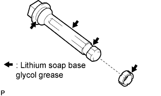
Apply lithium soap base glycol grease to the contact surface of the new cylinder slide bush and the cylinder slide pin.
-
Install the cylinder slide bush to the cylinder slide pin.
-
-
INSTALL FRONT DISC BRAKE CYLINDER SLIDE PIN
-
Install the cylinder slide pin to the cylinder mounting.
-
-
INSTALL FRONT DISC BRAKE CYLINDER MOUNTING
-
INSTALL FRONT DISC BRAKE ANTI-SQUEAL SHIM KIT
-
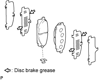
Apply disc brake grease to the 2 anti-squeal shims No.1 and install them to each pad.
-
Install the 3 anti-squeal shims to each pad.
-
Install the 2 pad wear indicator plates to the pads.
-
-
INSTALL FRONT DISC BRAKE PAD KIT
-
Install the 2 pads with pad wear indicator plates to the cylinder mounting.
-