BRAKE ACTUATOR (w/o VSC) INSTALLATION
-
INSTALL BRAKE ACTUATOR ASSEMBLY
-
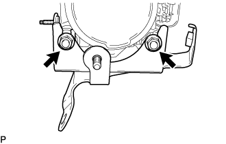
Install the brake actuator assembly to the actuator bracket with the 2 nuts.
- Torque:
- 5.4 N*m { 55 kgf*cm, 48 in.*lbf }
Note
-
Do not remove the hole plug until the new actuator assembly is connected because it already contains brake fluid.
-
Insert the protrusion of the actuator bolt holder between the positioning claws of the actuator bracket No.1.
-
Insert the positioning pin of the actuator bracket No.1 into the cushion of the actuator assembly.
-
-
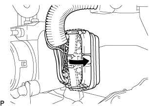
INSTALL BRAKE ACTUATOR COVER
-
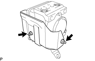
Install the actuator cover to the brake actuator assembly with the 2 nuts.
- Torque:
- 5.4 N*m { 55 kgf*cm, 48 in.*lbf }
-
-
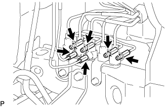
INSTALL BRAKE TUBE
-
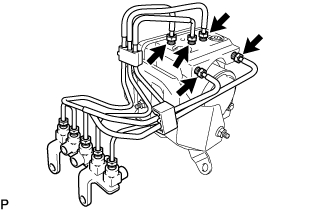
Using a union nut wrench, install the 5 brake tubes and brake way No.1 to the brake actuator assembly.
- Torque:
- 15 N*m { 155 kgf*cm, 11 ft.*lbf }
Note
Use the formula to calculate special torque values for situations where a union nut wrench is combined with a torque wrench Click here.
-
-
INSTALL BRAKE ACTUATOR ASSEMBLY WITH FRONT BRAKE TUBE WAY NO. 1
-
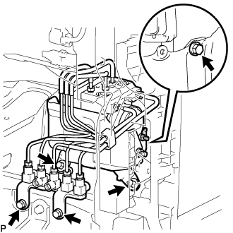
Install the brake actuator assembly with front brake tube way No. 1 and the brake tube to the body with the 5 bolts.
- Torque:
- 20 N*m { 204 kgf*cm, 15 ft.*lbf }
Note
Do not bend or damage the brake tube.
-
Using a union nut wrench, connect the 6 brake tubes to the front brake tube way No. 1.
- Torque:
- 15 N*m { 155 kgf*cm, 11 ft.*lbf }
Note
Use the formula to calculate special torque values for situations where a union nut wrench is combined with a torque wrench Click here.
-
Connect the connector and lock the lock lever.
Note
Check that the lock lever is securely locked.
-
-
INSTALL FRONT MUDGUARD
-
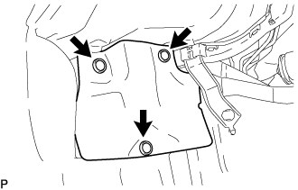
Install the front mudguard with the 3 clips.
-
-
INSTALL FRONT BUMPER
for Standard Body (See page Click here) for Wide Body (See page Click here) -
INSTALL FRONT WHEEL
- Torque:
- 100 N*m { 1020 kgf*cm, 74 ft.*lbf }
-
ADD BRAKE FLUID
Fluid SAE J1703 or FMVSS No. 116 DOT3 or equivalent -
BLEED BRAKE LINE
-
Connect the vinyl tube to the bleeder plug.
-
Depress the brake pedal several times and loosen the bleeder plug with the pedal held down.
-
At the point where the fluid stops coming out, tighten the bleeder plug and release the brake pedal.
-
Repeat this procedure until the air in the brake fluid is completely bled out.
-
Tighten the bleeder plug.
-
Front bleeder plug:
- Torque:
- 10.8 N*m { 110 kgf*cm, 8 ft.*lbf }
-
Rear bleeder plug:
- Torque:
- 11.0 N*m { 112 kgf*cm, 8 ft.*lbf }
-
-
Repeat the above procedure to bleed the air out of the brake line for each wheel.
-
-
INSPECT BRAKE FLUID LEVEL
-
Check the fluid level and add fluid if necessary.
Fluid SAE J1703 or FMVSS No.116 DOT3 or equivalent
-