STEERING ANGLE SENSOR (w/ VSC) INSTALLATION
-
INSPECT SPIRAL WITH SENSOR CABLE SUB-ASSEMBLY
-
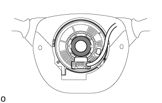
Check that the spiral cable sub-assembly is center position.
OK The connector is at the top. The matchmarks are aligned. The colored roller or the top of the flat cable U-turn can be checked from the check window. 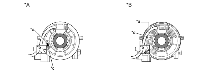
Text in Illustration *A Colored Roller (Visible Type) *B Flat Cable (Visible Type) *a Check Window *b Matchmark *c Colored Roller *d Top of Flat Cable U-turn -
If the spiral cable sub-assembly is not centered, center it.
Note
Failure to observe the following precautions may result in damage to the spiral cable sub-assembly.
-
When rotating the spiral cable sub-assembly, make sure to push on the interlock to release the interlock.
-
Do not turn the spiral cable sub-assembly using the airbag wire harness.
-
Do not forcibly rotate the part.
-
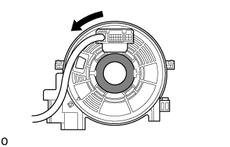
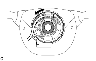
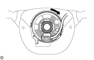
While pushing on the interlock indicated in the illustration. Make sure to rotate the spiral cable sub-assembly counterclockwise slowly by hand until it stops.
Note
Make sure to rotate the spiral cable sub-assembly counterclockwise. If rotated clockwise, it may be damaged or centering may no longer be possible.
Tech Tips
The interlock operates at the top and bottom of the connector.
Text in Illustration 
Interlock 
Counterclockwise -
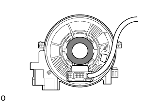
If the spiral cable sub-assembly stops rotating and the connector has moved past the bottom, return the connector to the bottom as shown in the illustration.
-
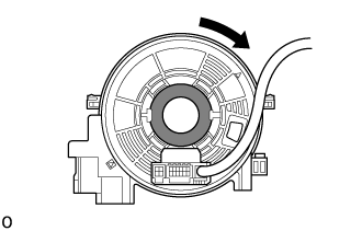
While pushing on the interlock, rotate the spiral cable sub-assembly clockwise approximately 2.5 times to move the connector from the bottom to the top.
Note
If the connector is rotated clockwise from the bottom 5 times or more, the spiral cable sub-assembly may be damaged.
Tech Tips
The interlock operates at the top and bottom of the connector.
Text in Illustration Interlock Counterclockwise -
Check that the spiral cable sub-assembly is center position.
OK The connector is at the top. The matchmarks are aligned. The colored roller or the top of the flat cable U-turn can be checked from the check window.
Text in Illustration *A Colored Roller (Visible Type) *B Flat Cable (Visible Type) *a Check Window *b Matchmark *c Colored Roller *d Top of Flat Cable U-turn Note
If the spiral cable sub-assembly cannot be centered, it is possible that the spiral cable sub-assembly is broken. Replace the spiral cable sub-assembly with a new one.
-
-
-
INSTALL SPIRAL WITH SENSOR CABLE SUB-ASSEMBLY
Note
-
Do not replace the spiral with sensor cable sub-assembly with the battery connected and the ignition switch on.
-
Do not rotate the spiral with sensor cable sub-assembly with the battery connected and the ignition switch on.
-
Check that the ignition switch is off.
-
Check that the spiral with sensor cable sub-assembly is disconnected from the negative (-) battery terminal.
CAUTION:
Wait at least 90 seconds after disconnecting the cable from the negative (-) battery terminal to disable the SRS system.
-
Check that the front wheels are facing straight ahead.
-
Attach the 3 claws to install the spiral with sensor cable sub-assembly.
Note
When replacing the spiral with sensor cable sub-assembly with a new one, remove the lock pin before installing the steering wheel assembly.
-
Connect each connector to the spiral with sensor cable sub-assembly.
Note
When connecting any airbag connector, take care not to damage the airbag wire harness.
-
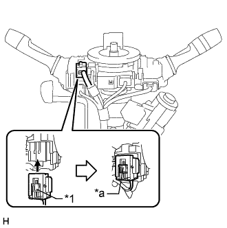
Text in Illustration *1 Slider *a Lock Position Connect the airbag connector and check that the slider is in the lock position.
Tech Tips
If the slider is not in the lock position, the airbag connector is not completely connected. Disconnect the airbag connector, check the airbag connector and spiral with sensor cable sub-assembly terminals and connector housings for deformation or foreign matter, and then reconnect the airbag connector.
-
-
INSTALL UPPER STEERING COLUMN COVER
-
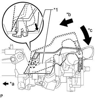
Text in Illustration *1 Column Tube *a Front of Vehicle *b Insert into the cutout of the column tube so that the claw of the steering column upper cover does not break *c Lower the backside of the steering column upper cover Install the steering column upper cover to the steering column assembly.
-
-
INSTALL LOWER STEERING COLUMN COVER
-
Engage the 4 claws to install the steering column lower cover to the steering column upper cover.
-
Using a "TORX" socket wrench (T25), tighten the 2 screws.
-
-
INSTALL NO. 2 STEERING COLUMN LOWER COVER (w/ Smart Entry and Start System)
-
Install the 4 guide pins install the No. 2 steering column lower cover.
-
-
TURN FRONT WHEELS TO FACE STRAIGHT AHEAD
-
ADJUST SPIRAL WITH SENSOR CABLE SUB-ASSEMBLY
-
Check that the ignition switch is off.
-
Check that the cable is disconnected from the negative (-) battery terminal.
CAUTION:
Wait at least 90 seconds after disconnecting the cable from the negative (-) battery terminal to disable the SRS system.
-
Check that the spiral cable sub-assembly is center position.
OK The connector is at the top. The colored roller or the top of the flat cable U-turn can be checked from the check window. 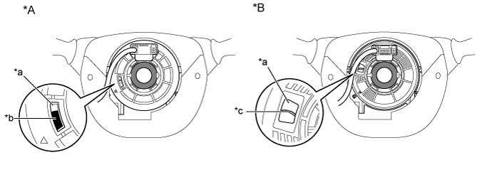
Text in Illustration *A Colored Roller (Visible Type) *B Flat Cable (Visible Type) *a Check Window *b Colored Roller *c Top of Flat Cable U-turn - - -
If the spiral cable sub-assembly is not centered, center it.
Note
Failure to observe the following precautions may result in damage to the spiral cable sub-assembly.
-
When rotating the spiral cable sub-assembly, make sure to push on the interlock to release the interlock.
-
Do not turn the spiral cable sub-assembly using the airbag wire harness.
-
Do not forcibly rotate the part.
-
While pushing on the interlock indicated in the illustration. Make sure to rotate the spiral cable sub-assembly counterclockwise slowly by hand until it stops.
Note
Make sure to rotate the spiral cable sub-assembly counterclockwise. If rotated clockwise, it may be damaged or centering may no longer be possible.
Tech Tips
The interlock operates at the top and bottom of the connector.
Text in Illustration Interlock Counterclockwise -
If the spiral cable sub-assembly stops rotating and the connector has moved past the bottom, return the connector to the bottom as shown in the illustration.
-
While pushing on the interlock, rotate the spiral cable sub-assembly clockwise approximately 2.5 times to move the connector from the bottom to the top.
Note
If the connector is rotated clockwise from the bottom 5 times or more, the spiral cable sub-assembly may be damaged.
Tech Tips
The interlock operates at the top and bottom of the connector.
Text in Illustration Interlock Counterclockwise -
Check that the spiral cable sub-assembly is center position.
OK The connector is at the top. The colored roller or the top of the flat cable U-turn can be checked from the check window.
Text in Illustration *A Colored Roller (Visible Type) *B Flat Cable (Visible Type) *a Check Window *b Colored Roller *c Top of Flat Cable U-turn - - Note
If the spiral cable sub-assembly cannot be centered, it is possible that the spiral cable sub-assembly is broken. Replace the spiral cable sub-assembly with a new one.
-
-
-
INSTALL STEERING WHEEL ASSEMBLY
-
CONNECT CABLE TO NEGATIVE BATTERY TERMINAL
Note
When disconnecting the cable, some systems need to be initialized after the cable is reconnected Click here.
-
INSPECT STEERING PAD
-
With the steering pad installed on the vehicle, perform a visual check. If there are any defects as mentioned below, replace the steering pad with a new one:
Cuts, small cracks or marked discoloration on the steering pad top surface or in the grooved portion.
-
Make sure that the horn sounds.
Tech Tips
If the horn does not sound, inspect the horn system Click here.
-
-
CHECK SRS WARNING LIGHT