VEHICLE STABILITY CONTROL SYSTEM, Diagnostic DTC:C120B
| DTC Code | DTC Name |
|---|---|
| C120B | IG Supply Voltage Low |
DESCRIPTION
| DTC No. | DTC Detection Condition | Trouble Area |
|---|---|---|
| C120B | Master cylinder pressure sensor power supply voltage decrease occurs or history of voltage decrease exists, and defective master cylinder pressure sensor output continues for 1 second or more. |
|
WIRING DIAGRAM
Refer to DTC C1241 Click here.
INSPECTION PROCEDURE
Note
-
When replacing the skid control ECU (brake actuator assembly), perform zero point calibration and store system information Click here.
-
Inspect the fuses for circuits related to this system before performing the following procedure.
PROCEDURE
-
CHECK HARNESS AND CONNECTOR (+BS TERMINAL)
-
Turn the ignition switch off.
-
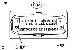
Text in Illustration *a Front view of wire harness connector
(to Skid Control ECU (Brake Actuator Assembly))
Make sure that there is no looseness at the locking part and the connecting part of the connector.
-
Disconnect the B92 skid control ECU (brake actuator assembly) connector.
-
Measure the voltage according to the value(s) in the table below.
Standard Voltage Tester Connection Condition Specified Condition B92-38 (+BS) - Body ground Always 11 to 14 V B92-38 (+BS) - B92-25 (GND1) Always 11 to 14 V
NG 
REPAIR OR REPLACE HARNESS OR CONNECTOR (+BS CIRCUIT)
OK 
-
-
RECONFIRM DTC
-
Reconnect the B92 skid control ECU (brake actuator assembly) connector.
-
Clear the DTCs Click here.
-
Check if the same DTC is recorded Click here.
Result Result Proceed to DTC C120B is not output A DTC C120B is output B
B
REPLACE BRAKE ACTUATOR ASSEMBLY Click here
A 
USE SIMULATION METHOD TO CHECK Click here
-