ANTI-LOCK BRAKE SYSTEM, Diagnostic DTC:C1241/41
| DTC Code | DTC Name |
|---|---|
| C1241/41 | Low Battery Positive Voltage |
DESCRIPTION
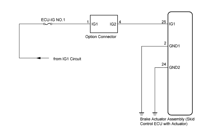
If there is a problem with the brake actuator assembly (skid control ECU) power supply circuit, the skid control ECU outputs the DTC and prohibits the ABS operation with the fail safe function.
If the voltage supplied to the IG1 terminal is not within the DTC detection threshold due to malfunctions in such as the battery and alternator circuit, this DTC is stored.
| DTC No. | DTC Detection Condition | Trouble Area |
|---|---|---|
| C1241/41 | When any of the following is detected:
|
|
WIRING DIAGRAM
INSPECTION PROCEDURE
Tech Tips
After steps 1 and 2 are completed, start the inspection from step 3 when using the intelligent tester, and from step 4 when not using the intelligent tester.
PROCEDURE
-
INSPECT BATTERY
-
Check the battery voltage.
Standard voltage 11 to 14 V
NG 
INSPECT CHARGING SYSTEM
OK 
-
-
INSPECT FUSE (ECU-IG NO. 1 FUSE)
-
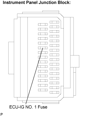
Remove the ECU-IG NO. 1 fuse from the instrument panel junction block.
-
Measure the resistance according to the value(s) in the table below.
Standard resistance Tester Connection Specified Condition ECU-IG NO. 1 (7.5 A) fuse Below 1 Ω (Continuity)
NG
REPLACE FUSE (ECU-IG NO.1 FUSE)
OK
-
-
READ VALUE USING INTELLIGENT TESTER (IG1 POWER SUPPLY)
-
Install the ECU-IG NO. 1 fuse.
-
Connect the intelligent tester to the DLC3.
-
Turn the ignition switch to the ON position and turn the intelligent tester main switch on.
-
Start the engine.
-
Select the DATA LIST mode on the intelligent tester.
ABS: Item (Display) Measurement Item / Range (Display) Normal Condition Diagnostic Note ECU IG Power Voltage ECU IG power supply voltage / TOO LOW/NORMAL TOO LOW: 9.5 V or less
NORMAL: 9.5 to 14.0 V
- -
Measure the voltage output from the ECU displayed on the intelligent tester.
OK "Normal" is displayed.
NG
REPAIR OR REPLACE HARNESS OR CONNECTOR (IG1 CIRCUIT)
OK
-
-
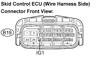
INSPECT SKID CONTROL ECU (IG1 TERMINAL VOLTAGE)
-
Disconnect the skid control ECU connector.
-
Turn the ignition switch to ON position.
-
Measure the voltage according to the value(s) in the table below.
Standard voltage Tester Connection Specified Condition B19-25 (IG1) - Body ground 10 to 14 V
NG
REPAIR OR REPLACE HARNESS OR CONNECTOR (IG1 CIRCUIT)
OK
-
-
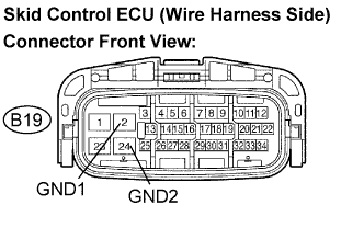
INSPECT SKID CONTROL ECU (GND TERMINAL CONTINUITY)
-
Turn the ignition switch off.
-
Measure the resistance according to the value(s) in the table below.
Standard resistance Tester Connection Specified Condition B19-2 (GND1) - Body ground Below 1 Ω B19-24 (GND2) - Body ground Below 1 Ω
NG
REPAIR OR REPLACE HARNESS OR CONNECTOR (GND CIRCUIT)
OK
-
-
RECONFIRM DTC
-
Clear the DTCs Click here.
-
Check that the same DTC is recorded Click here.
Tech Tips
Reinstall the sensors, connectors, etc. and restore the vehicle to its prior condition before rechecking for DTCs.
Result Condition Proceed to DTC (C1241/41) is output A DTC (C1241/41) is not output (When troubleshooting in accordance with the DTC CHART) B DTC (C1241/41) is not output (When troubleshooting in accordance with the PROBLEM SYMPTOMS TABLE) C
B
END
C
PROCEED TO NEXT CIRCUIT INSPECTION SHOWN IN PROBLEM SYMPTOMS TABLE
A 
REPLACE BRAKE ACTUATOR ASSEMBLY
-