ANTI-LOCK BRAKE SYSTEM, Diagnostic DTC:C1337/37
| DTC Code | DTC Name |
|---|---|
| C1337/37 | Diameter of the Tire is not Uniform |
DESCRIPTION
The skid control ECU measures the speed of each wheel by receiving signals from the speed sensors. These signals are used for recognizing that all 4 wheels are operating properly. Therefore, all wheel signals must be equal.
| DTC No. | DTC Detection Condition | Trouble Area |
|---|---|---|
| C1337/37 | With the vehicle speed 20 km/h (12 mph) or higher, an average vehicle speed difference between the front and rear wheels continuously exceeding 20% for 20 seconds is detected 3 times consecutively. |
|
WIRING DIAGRAM
Front speed sensor circuit: Refer to DTCs C0200/31, C0205/32, C1235/35 and C1236/36 Click here.
Rear speed sensor circuit: Refer to DTCs C0210/33, C0215/34, C1238/38 and C1239/39 Click here.
INSPECTION PROCEDURE
PROCEDURE
-
CHECK TIRE SIZE
-
Check the size and condition of all 4 tires.
NG 
REPLACE TIRES SO THAT ALL 4 TIRES ARE SAME IN SIZE
OK 
-
-
CHECK HARNESS AND CONNECTOR (BRAKE ACTUATOR ASSEMBLY - SPEED SENSOR)
-
Turn the ignition switch off.
-
Make sure that there is no looseness at the locking part and the connecting part of the connectors.
-
Disconnect the B19 skid control ECU (brake actuator assembly) connector and the B18, B20 and/or P1 speed sensor connector.
-
Measure the resistance according to the value(s) in the table below.
Standard Resistance for Front RH Tester Connection Condition Specified Condition B19-31 (FR+) - B18-2 Always Below 1 Ω B19-31 (FR+) or B18-2 - Body ground Always 10 kΩ or higher B19-30 (FR-) - B18-1 Always Below 1 Ω B19-30 (FR-) or B18-1 - Body ground Always 10 kΩ or higher for Front LH Tester Connection Condition Specified Condition B19-9 (FL+) - B20-2 Always Below 1 Ω B19-9 (FL+) or B20-2 - Body ground Always 10 kΩ or higher B19-8 (FL-) - B20-1 Always Below 1 Ω B19-8 (FL-) or B20-1 - Body ground Always 10 kΩ or higher for Rear RH Tester Connection Condition Specified Condition B19-33 (RR+) - P1-4 (RR+) Always Below 1 Ω B19-33 (RR+) or P1-4 (RR+) - Body ground Always 10 kΩ or higher B19-34 (RR-) - P1-3 (RR-) Always Below 1 Ω B19-34 (RR-) or P1-3 (RR-) - Body ground Always 10 kΩ or higher for Rear LH Tester Connection Condition Specified Condition B19-11 (RL+) - P1-2 (RL+) Always Below 1 Ω B19-11 (RL+) or P1-2 (RL+) - Body ground Always 10 kΩ or higher B19-12 (RL-) - P1-1 (RL-) Always Below 1 Ω B19-12 (RL-) or P1-1 (RL-) - Body ground Always 10 kΩ or higher Result Result Proceed to OK (for Rear LH) A OK (for Front RH, Front LH or Rear RH) B NG C
B 
INSPECT BRAKE ACTUATOR ASSEMBLY Click here
C
REPAIR OR REPLACE HARNESS OR CONNECTOR
A
-
-
INSPECT REAR SPEED SENSOR RH
-
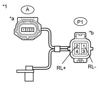
Text in Illustration *1 Rear Speed Sensor RH *a Front view of wire harness connector
(to Sensor Side Connector)
*b Front view of wire harness connector
(to Vehicle Side Connector)
Turn the ignition switch off.
-
Make sure that there is no looseness at the locking part and the connecting part of the connectors.
-
Disconnect the A rear speed sensor RH connector.
-
Measure the resistance according to the value(s) in the table below.
Standard Resistance Tester Connection Condition Specified Condition A-3 - P1-1 (RL-) Always Below 1 Ω A-3 or P1-1 (RL-) - Body ground Always 10 kΩ or higher A-1 - P1-2 (RL+) Always Below 1 Ω A-1 or P1-2 (RL+) - Body ground Always 10 kΩ or higher Note
Check the speed sensor signal after replacement Click here.
NG
REPLACE REAR SPEED SENSOR RH Click here
OK
-
-
INSPECT BRAKE ACTUATOR ASSEMBLY
-
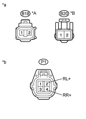
Text in Illustration *A for Front RH *B for Front LH *a Front view of wire harness connector
(to Front Speed Sensor)
*b Front view of wire harness connector
(to Rear Speed Sensor RH)
Reconnect the B19 skid control ECU (brake actuator assembly) connector.
-
Turn the ignition switch to ON.
-
Measure the voltage according to the value(s) in the table below.
Standard Voltage for Front RH Tester Connection Switch Condition Specified Condition B18-2 - Body ground Ignition switch ON 5.7 to 14 V for Front LH Tester Connection Switch Condition Specified Condition B20-2 - Body ground Ignition switch ON 5.7 to 14 V for Rear RH Tester Connection Switch Condition Specified Condition P1-4 (RR+) - Body ground Ignition switch ON 5.7 to 14 V for Rear LH Tester Connection Switch Condition Specified Condition P1-2 (RL+) - Body ground Ignition switch ON 5.7 to 14 V
NG
REPLACE BRAKE ACTUATOR ASSEMBLY
OK
-
-
RECONFIRM DTC
-
Disconnect the B18, B20 and/or P1 speed sensor connector.
-
Clear the DTCs Click here.
-
Drive the vehicle at a speed of approximately 30 km/h (19 mph) or more for 60 seconds or more.
-
Check that the same DTC is recorded Click here.
Result Result Proceed to DTC is not output A DTC is output B
B
INSPECT SPEED SENSOR TIP Click here
A 
USE SIMULATION METHOD TO CHECK Click here
-
-
INSPECT SPEED SENSOR TIP
-
Remove the front speed sensor Click here.
-
Remove the rear speed sensor Click here.
-
Check the sensor tip.
OK No scratches or foreign matter on the sensor tip. Note
-
If no damage to the speed sensor tip is found during this inspection, do not replace the speed sensor.
-
If there is iron powder sticking to the rotor, this will result in a malfunction, so confirm that the rotor is not contaminated with foreign material before replacing the sensor.
-
Check the speed sensor signal after cleaning or replacement Click here.
-
NG
CLEAN OR REPLACE SPEED SENSOR
OK
CLEAN OR REPLACE SKID CONTROL ROTOR
-