FRONT AXLE HUB REMOVAL

-
REMOVE FRONT WHEEL
-
SEPARATE FRONT SPEED SENSOR (w/ ABS)
-
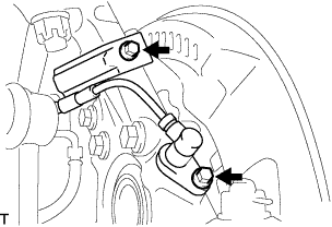
Remove the 2 bolts, and separate the speed sensor from the steering knuckle.
Note
-
Be careful not to damage the speed sensor.
-
Prevent foreign matter from adhering to the speed sensor.
-
-
-
SEPARATE FRONT DISC BRAKE CALIPER ASSEMBLY
-
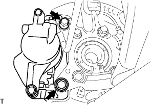
Remove the 2 bolts, and disconnect the brake caliper assembly.
Note
Use a wire or an equivalent to keep the brake caliper from hanging down by the flexible hose.
-
-
SEPARATE TIE ROD END SUB-ASSEMBLY
-
Remove the cotter pin and castle nut.
-
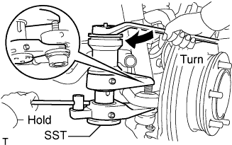
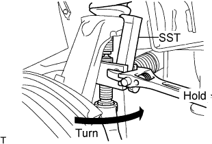
Using SST, separate the tie rod end from the steering knuckle.
- SST
- 09628-00011
Note
-
Do not damage the ball joint dust boot.
-
Do not damage the brake dust cover.
-
Make sure that the string of the SST is securely tied to the vehicle.
-
-
REMOVE FRONT AXLE ASSEMBLY
-
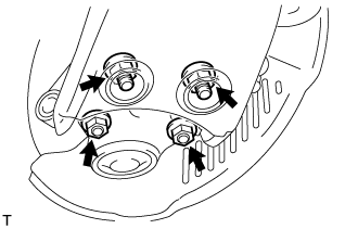
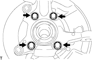
Remove the 4 bolts, 4 nuts and front axle assembly from the front suspension lower arm.
-
Remove the cotter pin and castle nut.
-
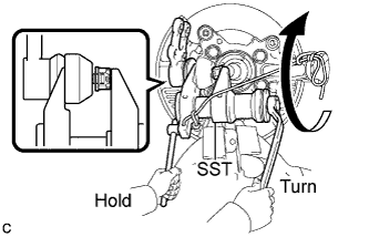
Using SST, remove the front axle assembly from the front suspension upper arm.
- SST
- 09628-62011
Note
-
Do not damage the ball joint dust boot.
-
Apply grease to the threads and tip of the SST center bolt before use.
-
Make sure that the string of the SST is securely tied to the vehicle.
-
-
REMOVE FRONT LOWER BALL JOINT ASSEMBLY
-
Fix the steering knuckle in the vise using aluminium plates.
Note
Do not damage the steering knuckle.
-
Remove the cotter pin.
-
Loosen the nut.
-
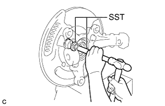
Using SST, separate the front lower ball joint assembly from the steering knuckle.
- SST
- 09628-00011
Note
-
Do not damage the ball joint dust boot.
-
Make sure that the string of the SST is securely tied to the steering knuckle.
-
Remove the nut and front lower ball joint assembly.
-
-
REMOVE INNER KNUCKLE GREASE RETAINER CAP (w/ Cap)
-
Using a chisel, make a hole in the center of the outer knuckle grease retainer cap to insert a brass bar.
-
Using a brass bar, remove the inner knuckle grease retainer cap from the steering knuckle as shown in the illustration.
-
-
REMOVE OUTER KNUCKLE GREASE RETAINER CAP (w/ Cap)
-
Using SST, remove the outer knuckle grease retainer cap.
- SST
- 09950-60010 ( 09951-00300 )
- 09950-70010 ( 09951-07200 )
-
-
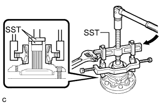
REMOVE STEERING KNUCKLE
-
Remove the 4 bolts.
-
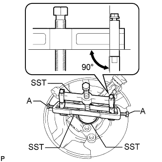
Using SST, remove the steering knuckle, brake dust cover from the front axle hub sub-assembly.
- SST
- 09950-40011 ( 09951-04020, 09952-04010, 09953-04010, 09958-04011 )
- 09950-60010 ( 09951-00470 )
- 09955-04140
- 09958-04030
Note
-
Apply grease to the threads and tip of the SST center bolt (09953-04010) before use.
-
Make sure that the slide arm (09952-04010) is at a 90° angle to the hanger 200 (09951-04020) when using SST.
-
Make sure that the claw No. 14 (09955-04140) is securely attached to the steering knuckle.
Tech Tips
For bolt A, use the bolt for the holder (09958-04011).
-
-
REMOVE FRONT WHEEL ADJUSTING NUT (w/ ABS)
-
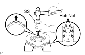
Install the hub nut to the front axle hub bolt.
-
Hold the axle hub and bearing assembly in a vise between aluminium plates.
Note
-
Do not overtighten the vise.
-
Hold the hub nut in a vise to secure the axle hub and bearing assembly.
-
-
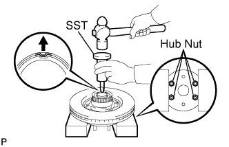
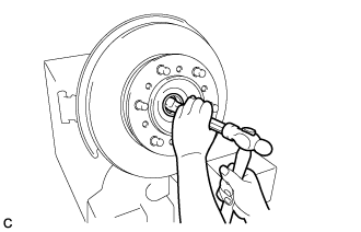
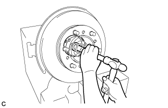
Using SST and a hammer, release the staked part of the front wheel adjusting nut.
- SST
- 09930-00010
Note
Release the staked part of the nut completely, otherwise the threads of the front axle hub may be damaged.
-

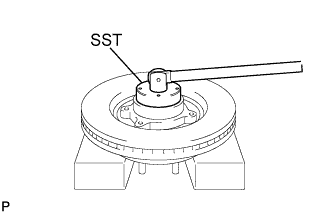
Using SST, remove the front wheel adjusting nut and skid control rotor.
- SST
- 09607-26010
Note
Do not use an extension bar to avoid applying excess torque to the nut and rotor.
-
-
REMOVE FRONT WHEEL ADJUSTING NUT (w/o ABS)
-
Install the hub nut to the front axle hub bolt.
-
Hold the axle hub and bearing assembly in a vise between aluminium plates.
Note
-
Do not overtighten the vise.
-
Hold the hub nut in a vise to secure the axle hub and bearing assembly.
-
-
Using SST and a hammer, release the staked part of the front wheel adjusting nut.
- SST
- 09930-00010
Note
Release the staked part of the nut completely, otherwise the threads of the front axle hub may be damaged.
-
Using SST, remove the front wheel adjusting nut and front wheel bearing dust deflector No.1.
- SST
- 09607-26010
Note
Do not use an extension bar to avoid applying excess torque to the nut and rotor.
-
-
REMOVE FRONT DISC
-
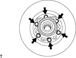
Remove the 6 bolts.
-
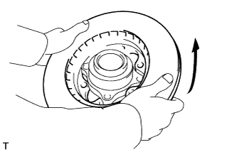
Remove the front disc as shown in the illustration.
-
-
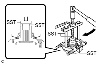
REMOVE FRONT AXLE HUB BEARING
-
Using SST, remove the front axle hub bearing from the front axle hub sub-assembly.
- SST
- 09950-40011 ( 09951-04020, 09952-04010, 09953-04020, 09954-04010, 09955-04031, 09957-04010, 09958-04011 )
- 09950-60010 ( 09951-00360, 09951-00480, 09952-06010 )
Note
Apply a small amount of grease to the threads and tip of SST (center bolt) before use.
-
Using SST, remove the front axle hub bearing (inner race) from the front axle hub sub-assembly.
- SST
- 09950-00020
- 09950-00030
- 09950-40011 ( 09957-04010 )
- 09950-60010 ( 09951-00360, 09951-00480, 09952-06010 )
Note
Apply a small amount of grease to the threads and tip of SST (center bolt) before use.
-