DIFFERENTIAL CARRIER ASSEMBLY REASSEMBLY

-
INSTALL REAR DIFFERENTIAL DUST DEFLECTOR
-
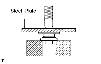
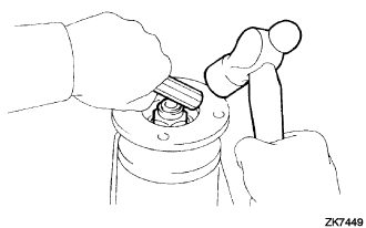
Using steel plate and a press, install a new dust deflector.
Note
-
Slowly press in the dust deflector.
-
If any burrs remain after pressing in the deflector, remove them.
-
-
-
ASSEMBLE DIFFERENTIAL CASE (2 Pinion Type)
-
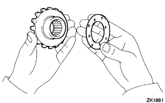
Install the 2 side gear thrust washers to the 2 side gears.
Note
-
Make sure that there is no dirt or foreign matter on the thrust washer, side gear, etc. before installing them.
-
If replacing either the side gear or pinion, replace them as a set.
-
Apply hypoid gear oil to all sliding and rotating parts.
-
-
Install the 2 side gears, 2 pinions, 2 pinion thrust washers and pinion shaft to the differential case.
Note
Align the holes of the differential case and pinion shaft.
-
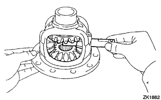
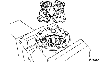
Hold the differential case in a vise between aluminum plates.
Note
Do not overtighten the vise.
-
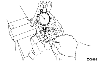
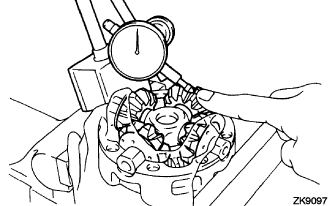
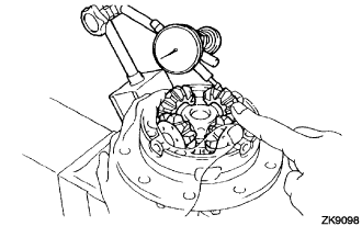
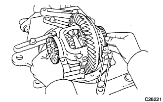
Using a dial indicator, measure the side gear backlash while holding the pinion toward the differential case.
Backlash 0.05 to 0.20 mm (0.0020 to 0.0079 in.) If the backlash is not within the specification, install the 2 side gear thrust washers of different thicknesses.
Tech Tips
Refer to the following table to select the 2 side gear thrust washers.
Side gear thrust washer thickness Part No. Thickness mm (in.) 41361-40021 1.57 to 1.63 (0.0618 to 0.0642) 41362-40021 1.67 to 1.73 (0.0658 to 0.0681) 41363-40021 1.77 to 1.83 (0.0697 to 0.0721) -
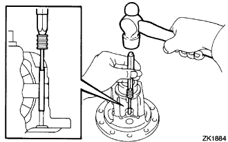
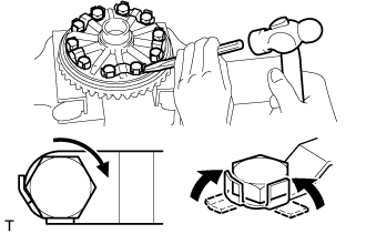
Using a pin punch (5 mm) and a hammer, install the pinion shaft pin through the differential case and hole of the pinion shaft.
-
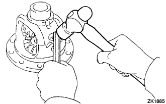
Using a chisel and a hammer, stake the outside of the differential case pin hole.
-
-
ASSEMBLE DIFFERENTIAL CASE (4 Pinion Type)
-
Install the 2 side gear thrust washers to the 2 side gears.
Note
-
Make sure that there is no dirt or foreign matter on the thrust washer, side gear, etc. before installing them.
-
If replacing either the side gear or pinion, replace them as a set.
-
Apply hypoid gear oil to all sliding and rotating parts.
-
-
Install the 4 pinion thrust washers and 4 pinions onto the spider.
-
Fix the differential case RH.
-
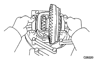
Install the side gear and spider onto the differential case RH.
-
Using a dial indicator, measure the differential case RH side backlash while holding the pinion toward the case.
Backlash 0.05 to 0.20 mm (0.002 to 0.008 in.) Note
Inspect the backlash at several locations on each of the 4 pinions.
-
Remove the spider from the differential case RH.
-
Install the side gear and spider onto the differential case LH.
-
Using a dial indicator, measure the differential case LH side backlash while holding the pinion toward the case.
Backlash 0.05 to 0.20 mm (0.002 to 0.008 in.) Note
Inspect the backlash at several locations on each of the 4 pinions.
If the backlash is not within the specification, install 2 side gear thrust washers of a different thickness.
Side gear thrust washer thickness Part No. Thickness mm (in.) 41361-35310 0.87 to 0.93 (0.0343 to 0.0366) 41361-35320 0.97 to 1.03 (0.0382 to 0.0406) 41361-35330 1.07 to 1.13 (0.0421 to 0.0445) 41361-35340 1.17 to 1.23 (0.0461 to 0.0484) 41361-35350 1.27 to 1.33 (0.0500 to 0.0524) -
Align the matchmarks and assemble the RH and LH cases.
-
Using a plastic hammer, install the differential case.
-
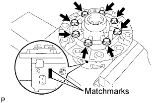
Install the 8 bolts.
- Torque:
- 47 N*m { 480 kgf*cm, 35 ft.*lbf }
Tech Tips
Tighten the bolts gradually, always skipping to a diagonally opposite bolt.
-
-
INSTALL DIFFERENTIAL RING GEAR
-
Clean the contact surfaces of the differential case and ring gear.
-
Clean the differential ring gear set bolt hole.
-
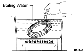
Heat the ring gear to approx. 100°C (212°F) in boiling water.
CAUTION:
Use thick gloves to protect hands as the ring gear is hot.
-
Carefully take the ring gear out of the boiling water.
-
Hold the differential case in a vise between aluminum plates.
Note
Do not overtighten the vise.
-
After the moisture on the ring gear has completely evaporated, quickly install the ring gear to the differential case.
-
Align the matchmarks on the ring gear and differential case.
-
Temporarily install 5 new lock plates and 10 bolts.
-
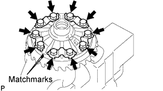
After the ring gear cools down, tighten the 10 bolts uniformly.
- Torque:
- 97 N*m { 985 kgf*cm, 72 ft.*lbf }
Tech Tips
-
Tighten the bolts gradually, always skipping to a diagonally opposite bolt.
-
Ensure that the ring gear is sufficiently cool before tightening the bolts.
-
Using a chisel and a hammer, stake the 5 lock plates.
-
Stake one claw so that it is flush against the flat surface of the bolt.
-
Stake the other claw against the surface of the bolt head to act as a stopper if the bolt starts to loosen.
-
-
-
INSTALL REAR DIFFERENTIAL CASE BEARING
-
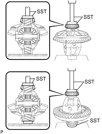
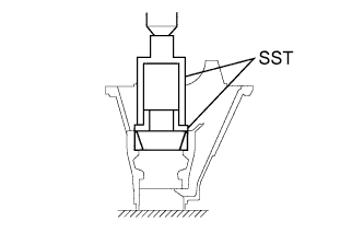
Using SST and a press, install the case bearing inner races LH and RH to the differential case.
- SST
- 09950-60010 ( 09951-00480, 09951-00550 )
- 09950-70010 ( 09951-07150 )
Note
-
Do not apply hypoid gear oil to a new bearing.
-
Do not deform the bearing cage.
-
Set SST to the center of the differential case.
-
If the bearing is replaced, replace it and the outer race as a set.
-
-
INSPECT DIFFERENTIAL RING GEAR RUNOUT
-
Install the case bearing outer races LH and RH to the case bearing inner races LH and RH respectively.
Note
Be sure to install the bearing outer races in each correct position.
-
Install the differential case to the differential carrier.
-
Install the 2 bearing adjusting nuts.
-
Install the right and left bearing caps with the 4 bolts.
- Torque:
- 85 N*m { 870 kgf*cm, 63 ft.*lbf }
-
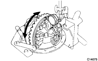
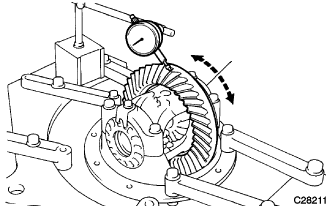
Using a dial indicator, measure the runout of the ring gear.
Maximum runout 0.07 mm (0.0028 in.) Tech Tips
Measure at a radial position 92 mm (3.62 in.) from the center of the ring gear.
If the runout is greater than the maximum, replace the drive pinion, ring gear and differential case.
-
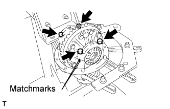
Remove the right and left bearing caps and differential case.
-
-
INSTALL REAR DRIVE PINION REAR BEARING
-
Using SST and a press, install the outer race of the rear drive pinion rear tapered roller bearing to the differential carrier.
- SST
- 09316-60011 ( 09316-00011, 09316-00041 )
-
-
INSTALL REAR DRIVE PINION FRONT BEARING
-
Using SST and a press, install the outer race of the rear drive pinion front tapered roller bearing to the differential carrier.
- SST
- 09316-60011 ( 09316-00011, 09316-00021 )
-
-
INSTALL REAR DRIVE PINION REAR BEARING
-
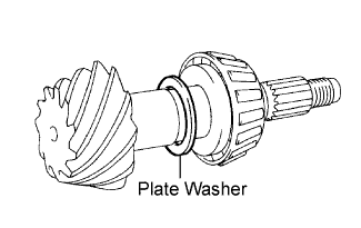
Install the drive pinion plate washer to the drive pinion.
-
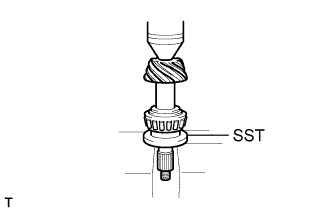
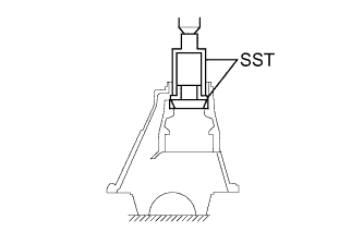
Using SST and a press, install the inner race of the rear drive pinion rear tapered roller bearing to the drive pinion.
- SST
- 09506-30012
-
-
ADJUST DIFFERENTIAL DRIVE PINION PRELOAD
-
Install the drive pinion and the inner race of the rear drive pinion front tapered roller bearing and oil slinger to the differential carrier.
-
Using SST, install the companion flange.
- SST
- 09950-30012 ( 09951-03010, 09953-03010, 09954-03010, 09955-03030, 09956-03040 )
Note
Apply grease to the threads and tip of the SST center bolt before use.
-
Coat the threads of the drive pinion nut with hypoid gear oil LSD.
-
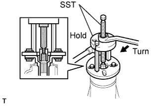
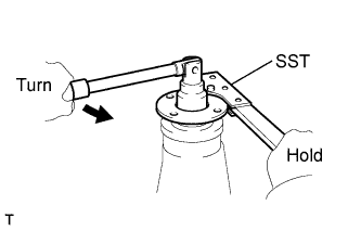
Using SST, hold the flange.
- SST
- 09330-00021
-
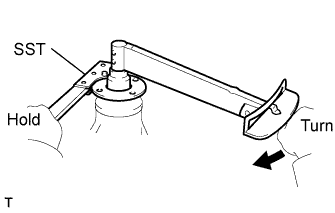
Using a socket wrench (30 mm) and torque wrench, gradually tighten the drive pinion nut within the adjustment range of the differential drive pinion preload.
Torque 370 N*m (3,770 kgf*cm, 273 ft.*lbf) or less Note
As there is no bearing spacer, tighten the nut a little at a time and do not overtighten.
-
Turn the bearing clockwise and counterclockwise several times to stabilize it.
-
Using a socket wrench (30 mm) and torque wrench, measure the preload.
Drive pinion preload (at starting) New bearing 1.01 to 1.60 N*m (11 to 16 kgf*cm, 9 to 14 in.*lbf) Reused bearing 0.52 to 0.81 N*m (6 to 8 kgf*cm, 5 to 7 in.*lbf) Note
Record the preload for total preload measurement.
If the preload is not within the specified range, adjust the differential drive pinion preload or repair as necessary.
-
-
INSTALL DIFFERENTIAL CASE ASSEMBLY
-
Install the case bearing outer races LH and RH to the case bearing inner races LH and RH respectively.
Note
Be sure to install the bearing outer races in each correct position.
-
Install the differential case to the differential carrier.
Tech Tips
Make sure the right and left races are not interchanged.
-
-
INSTALL REAR DIFFERENTIAL BEARING ADJUSTING NUT
-
Install the 2 bearing adjusting nuts into the differential carrier, making sure the nuts are threaded properly.
-
Align the matchmarks on the bearing cap and differential carrier.
-
Install the right and left bearing caps with the 4 bolts.
- Torque:
- 85 N*m { 870 kgf*cm, 63 ft.*lbf }
Tech Tips
If the bearing cap does not fit tightly on the carrier, the adjusting nuts are not threaded properly. Reinstall the adjusting nuts if necessary.
-
-
ADJUST DIFFERENTIAL RING GEAR BACKLASH
-
Tighten the 4 bearing cap bolts to the specified torque, then loosen them to the point where the adjusting nuts can be turned by SST.
- Torque:
- 85 N*m { 870 kgf*cm, 63 ft.*lbf }
-
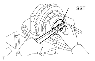
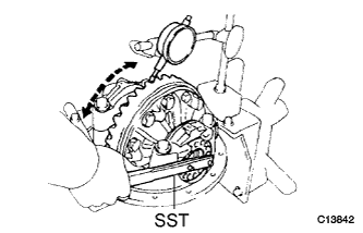
Using SST and dial indicator, tighten the adjusting nut on the ring gear back surface side so that the backlash of the ring is about 0.18 mm (0.0071 in.).
- SST
- 09504-00011
-
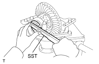
While turning the ring gear, use SST to fully tighten the adjusting nut on the ring gear tooth side. After the bearings have settled, loosen the adjusting nut on the ring gear tooth side.
- SST
- 09504-00011
-
Using SST, tighten the adjusting nut on the ring gear tooth side until the free play of the adjusting nut becomes 0.
Note
The free play becomes 0 when the adjusting nut becomes difficult to tighten.
-
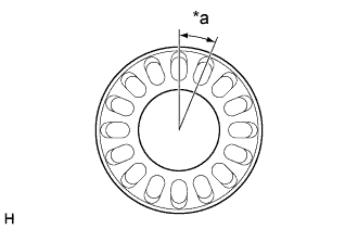
Text in Illustration *a 1 notch Tighten the adjusting nut on the ring gear tooth side 1.5 notches as shown in the illustration to apply preload to the side bearing.
Tech Tips
1 hole is equivalent to 1 notch.
-
Adjust the backlash between the drive pinion and ring gear to within the standard range by moving the bearing using the left and right adjusting nuts. (Tighten the right adjusting nut 1 notch for each notch loosened with the left nut.)
Backlash 0.13 to 0.18 mm (0.0051 to 0.0071 in.) Tech Tips
-
Tighten the right adjusting nut 1 notch for each notch loosened with the left nut in order to maintain the side bearing preload.
-
Measure the backlash at 3 or more points on the circumference of the ring gear.
-
Align the adjusting nut lock hole and adjusting nut hole.
-
-
Torque the 4 bearing cap bolts.
- Torque:
- 85 N*m { 870 kgf*cm, 63 ft.*lbf }
-
-
INSPECT TOTAL PRELOAD
-
Using a socket wrench (30 mm) and torque wrench, measure the preload.
Total preload (at starting) Drive pinion preload plus 0.39 to 0.59 N*m (4.0 to 6.0 kgf*cm, 3.5 to 5.2 in.*lbf) If the preload is not within the specified range, adjust it by the bearing adjusting nut on the ring gear teeth side.
-
-
INSPECT TOOTH CONTACT BETWEEN RING GEAR AND DRIVE PINION
-
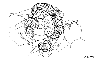
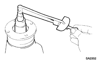
Coat 3 or 4 teeth at 3 different positions on the ring gear with prussian blue.
-
Rotate the ring gear in both directions.
-
Inspect the tooth contact pattern.
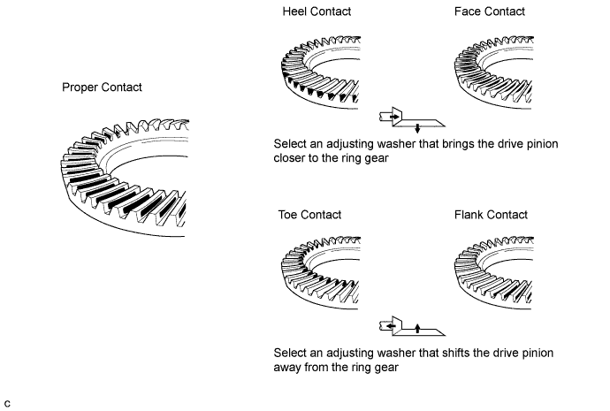
-
If the teeth are not contacting properly, use the following table to select a proper washer for correction.
Drive pinion plate washer thickness Part No. Thickness mm (in.) 90201-35497 1.69 to 1.71 (0.0665 to 0.0673) 90201-35498 1.72 to 1.74 (0.0677 to 0.0685) 90201-35499 1.75 to 1.77 (0.0689 to 0.0697) 90201-35500 1.78 to 1.80 (0.0701 to 0.0709) 90201-35501 1.81 to 1.83 (0.0713 to 0.0721) 90201-35502 1.84 to 1.86 (0.0724 to 0.0732) 90201-35503 1.87 to 1.89 (0.0736 to 0.0744) 90201-35504 1.90 to 1.92 (0.0748 to 0.0756) 90201-35505 1.93 to 1.95 (0.0760 to 0.0768) 90201-35506 1.96 to 1.98 (0.0772 to 0.0780) 90201-35507 1.99 to 2.01 (0.0784 to 0.0791) 90201-35508 2.02 to 2.04 (0.0795 to 0.0803) 90201-35509 2.05 to 2.07 (0.0807 to 0.0815) 90201-35510 2.08 to 2.10 (0.0819 to 0.0827) 90201-35511 2.11 to 2.13 (0.0831 to 0.0839) 90201-35512 2.14 to 2.16 (0.0843 to 0.0850) 90201-35513 2.17 to 2.19 (0.0854 to 0.0862) 90201-35514 2.20 to 2.22 (0.0866 to 0.0874) 90201-35515 2.23 to 2.25 (0.0878 to 0.0886) 90201-35516 2.26 to 2.28 (0.0890 to 0.0898) 90201-35517 2.29 to 2.31 (0.0902 to 0.0909) 90201-35518 2.32 to 2.34 (0.0913 to 0.0921)
-
-
REMOVE REAR DRIVE PINION NUT
-
Using SST, hold the flange.
- SST
- 09330-00021
-
Using a socket wrench (30 mm), remove the drive pinion nut.
-
-
REMOVE REAR DRIVE PINION COMPANION FLANGE SUB-ASSEMBLY
-
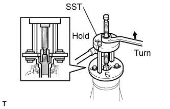
Using SST, remove the companion flange.
- SST
- 09950-30012 ( 09951-03010, 09953-03010, 09954-03010, 09955-03030, 09956-03040 )
Note
Apply grease to the threads and tip of the SST center bolt before use.
-
-
REMOVE REAR DIFFERENTIAL DRIVE PINION OIL SLINGER
-
REMOVE REAR DRIVE PINION FRONT BEARING
-
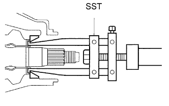
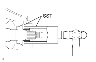
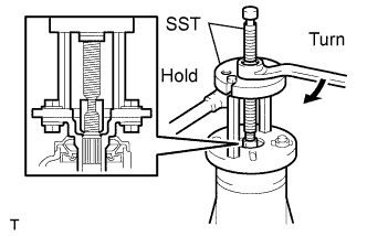
Using SST, remove the inner race of the rear drive pinion front tapered roller bearing from the drive pinion.
- SST
- 09556-22010
Note
Apply grease to the threads and tip of the SST center bolt before use.
-
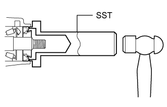
Using SST, remove the outer race of the rear drive pinion front tapered roller bearing from the differential carrier.
- SST
- 09308-00010
-
-
INSTALL REAR DIFFERENTIAL DRIVE PINION BEARING SPACER
-
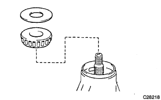
Install a new drive pinion bearing spacer to the drive pinion.
Note
Be sure to face the larger inner diameter side rearward as shown in the illustration.
-
-
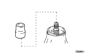
INSTALL DIFFERENTIAL OIL STORAGE RING
-
Using a brass bar and hammer, tap in a new oil storage ring.
Note
Be careful not to damage the oil storage ring.
-
-
INSTALL REAR DRIVE PINION FRONT BEARING
-
Using SST and hammer, tap in the outer race of the rear drive pinion front tapered roller bearing.
- SST
- 09316-60011 ( 09316-00011, 09316-00021 )
-
Install the inner race of the rear drive pinion front tapered roller bearing.
-
-
INSTALL REAR DIFFERENTIAL DRIVE PINION OIL SLINGER
-
INSTALL REAR DIFFERENTIAL CARRIER OIL SEAL
-
Using SST and a hammer, install a new oil seal.
- SST
- 09554-22010
Oil seal drive in depth 0.4 to 1.0 mm (0.0158 to 0.0393 in.) -
Apply MP grease to the oil seal lip.
-
-
INSTALL REAR DRIVE PINION COMPANION FLANGE SUB-ASSEMBLY
-
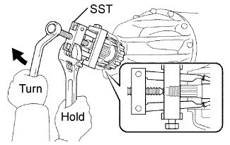
Using SST, install the companion flange to the drive pinion.
- SST
- 09950-30012 ( 09951-03010, 09953-03010, 09954-03010, 09955-03030, 09956-03040 )
Note
Apply grease to the threads and tip of the SST center bolt before use.
-
Coat the threads of a new drive pinion nut with hypoid gear oil LSD.
-
Using SST, hold the flange.
- SST
- 09330-00021
-
Using a socket wrench (30 mm) and torque wrench, gradually tighten the drive pinion nut within the adjustment range of the differential drive pinion preload.
Torque 370 N*m (3,770 kgf*cm, 273 ft.*lbf) or less
-
-
INSPECT DRIVE PINION PRELOAD
-
Turn the bearing clockwise and counterclockwise several times to stabilize it.
-
Using a socket wrench (30 mm) and torque wrench, measure the preload.
Preload (at starting) New bearing 1.01 to 1.60 N*m (11 to 16 kgf*cm, 9 to 14 in.*lbf) Reused bearing 0.52 to 0.81 N*m (6 to 8 kgf*cm, 5 to 7 in.*lbf) -
If the preload is less than the specified minimum value, check the preload while retightening the drive pinion nut by 5 to 10° to adjust it into the specified range.
-
If the preload is less than the specified minimum value even when the tightening torque of the drive pinion nut is greater than the specified maximum value, loosen the nut and check that the threads of the drive pinion nut and drive pinion are not stripped.
-
If the threads are not stripped, replace the bearing spacer. Apply hypoid gear oil LSD to the threads of the drive pinion and repeat the procedure.
-
-
INSPECT TOTAL PRELOAD
-
Using a socket wrench (30 mm) and torque wrench, measure the preload.
Total preload (at starting) Drive pinion preload plus 0.39 to 0.59 N*m (4.0 to 6.0 kgf*cm, 3.5 to 5.2 in.*lbf)
-
-
INSPECT DIFFERENTIAL RING GEAR BACKLASH
-
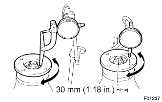
Set the dial indicator to the end of the differential ring gear face.
-
Rotate the differential ring gear and measure the backlash.
Backlash 0.13 to 0.18 mm (0.0051 to 0.0071 in.) Tech Tips
Inspect the backlash at 3 or more locations on the ring gear.
-
-
INSPECT RUNOUT OF REAR DRIVE PINION COMPANION FLANGE SUB-ASSEMBLY
-
Using a dial indicator, measure the runout of the companion flange vertically and horizontally.
Maximum runout 0.10 mm (0.0039 in.) If the runout is greater than the maximum value, replace the companion flange sub-assembly.
-
-
INSTALL REAR DRIVE PINION NUT
-
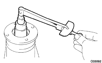
Using a chisel and hammer, stake the drive pinion nut.
-
-
INSTALL REAR DIFFERENTIAL BEARING ADJUSTING NUT LOCK
-
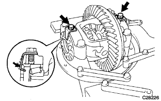
Install the 2 new bearing adjusting nut locks to the bearing caps.
-
Tighten both of the bearing adjusting nut locks with the 2 bolts.
- Torque:
- 13 N*m { 130 kgf*cm, 9 ft.*lbf }
-