DIFFERENTIAL CARRIER ASSEMBLY REMOVAL

-
REMOVE REAR WHEELS
-
DRAIN DIFFERENTIAL OIL
-
Remove the filler plug and gasket.
-
Remove the drain plug and gasket, and drain the oil.
-
-
DRAIN BRAKE FLUID
-
REMOVE REAR BRAKE DRUM SUB-ASSEMBLIES
-
Release the parking brake lever, and remove the brake drum.
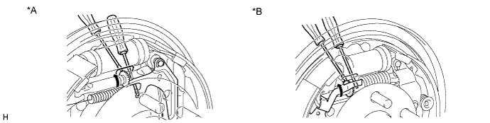
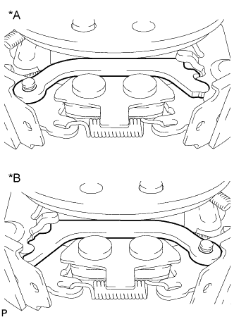
Text in Illustration *A for 295 mm Drum *B for 254 mm Drum Tech Tips
If the brake drum cannot be removed easily, perform the following steps.
-
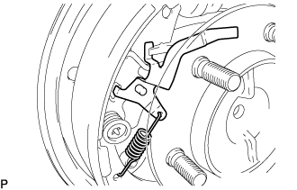
Remove the hole plug and insert a screwdriver through the hole in the backing plate, and hold the automatic adjusting lever away from the adjuster.
-
Using another screwdriver, contract the brake shoe adjuster by turning the adjusting wheel.
-
-
REMOVE REAR AXLE BRAKE DRUM GASKETS
-
REMOVE AUTOMATIC ADJUST LEVER LH
-
for 254 mm drum:
-
Remove the automatic adjust lever and the tension spring.
-
-
-
REMOVE AUTOMATIC ADJUST LEVER RH
Tech Tips
Removal procedure of the RH side is the same as that of the LH side.
-
SEPARATE PARKING BRAKE SHOE STRUT SET LH
-
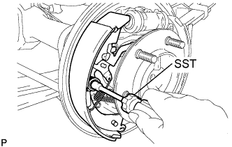
for 254 mm drum:
-
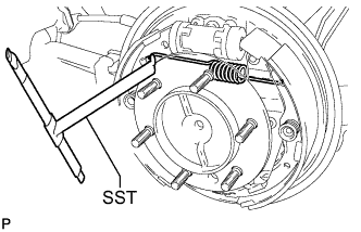
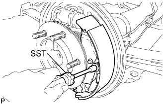
Using SST, remove the upper side tension spring from the brake shoe.
- SST
- 09703-30011
-
-
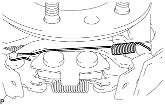
for 295 mm drum:
-
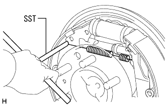
Using SST, remove the upper side tension spring from the brake shoe.
- SST
- 09703-30011
-
-
-
SEPARATE PARKING BRAKE SHOE STRUT SET RH
Tech Tips
Removal procedure of the RH side is the same as that of the LH side.
-
REMOVE FRONT BRAKE SHOES
-
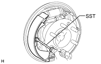
for 254 mm drum:
-
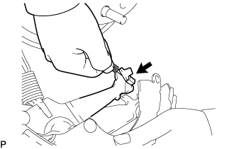
Using a needle-nose pliers, remove the anchor side tension spring.
-
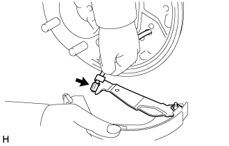
Using SST, remove the cup, shoe hold-down sprig and pin.
- SST
- 09718-00011
-
Text in Illustration *A LH Side *B RH Side Remove the parking brake shoe lower strut.
-
Separate the brake shoe return spring, and remove the front brake shoe.
-
-
for 295 mm drum:
-
Using SST, remove the cup, shoe hold-down sprig and pin.
- SST
- 09718-00011
-
Separate the brake shoe return spring, and remove the front brake shoe.
-
-
-
REMOVE REAR BRAKE SHOES
-
for 254 mm drum:
-
Using SST, remove the cup, shoe hold-down sprig and pin.
- SST
- 09718-00011
-
Disconnect the parking brake cable No. 3 and remove the rear brake shoe.
-
-
for 295 mm drum:
-
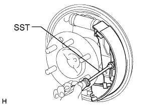
Using SST, remove the cup, shoe hold-down sprig and pin.
- SST
- 09718-00011
-
Remove the tension spring.
-
Disconnect the parking brake cable No. 3 and remove the rear brake shoe.
-
-
-
REMOVE PARKING BRAKE SHOE STRUT SET LH
-
for 254 mm drum:
-
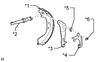
Text in Illustration *1 Brake Shoe Lever *2 Brake Shoe Strut Set *3 Rear Brake Shoe *4 Rear Cushion Lever *5 C-washer Using a screwdriver, remove the C-washer, brake shoe lever, rear cushion lever and brake shoe strut set from the brake shoe.
-
Remove the adjusting bolt and tension spring from the brake shoe strut set.
-
-
for 295 mm drum:
-
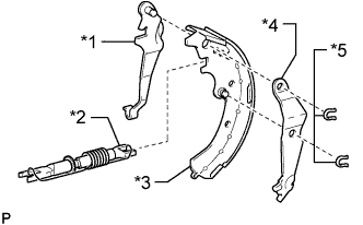
Text in Illustration *1 Rear Brake Shoe *2 Brake Shoe Strut Set *3 Brake Shoe Lever *4 Automatic Adjust Lever *5 C-washer *6 E-ring Remove the brake shoe strut set.
-
Using a screwdriver, remove the E-ring and automatic adjust lever.
-
Using a screwdriver, remove the C-washer and brake shoe lever from the brake shoe.
-
-
-
REMOVE PARKING BRAKE SHOE STRUT SET RH
Tech Tips
Removal procedure of the RH side is the same as that of the LH side.
-
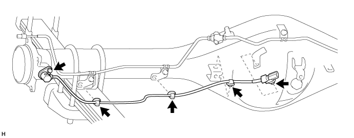
SEPARATE PARKING BRAKE CABLE ASSEMBLY NO. 3
-
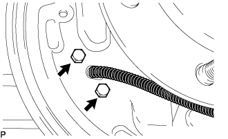
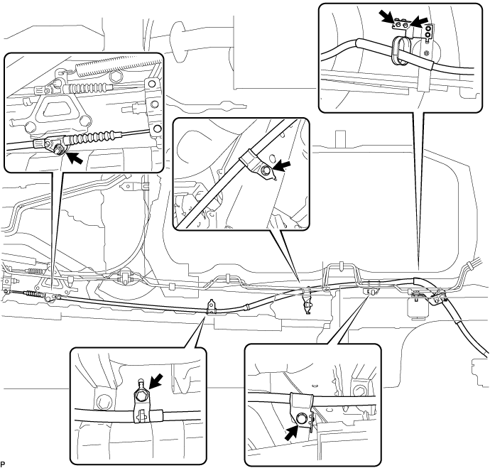
Remove the 2 bolts and separate the parking brake cable assembly No.3 from the backing plate.
-
Remove the 5 bolts, nut and parking brake cable assembly No.3.
-
Remove the parking brake cable assembly No.3 from the parking brake equalizer.
-
-
SEPARATE PARKING BRAKE CABLE ASSEMBLY NO. 2
Tech Tips
Removal procedure of the RH side is the same as that of the LH side.
-
REMOVE REAR WHEEL BRAKE CYLINDER ASSEMBLY LH
-
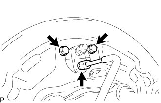
Using a union nut wrench, disconnect the brake tube, use a container to catch brake fluid.
-
Remove the 2 bolts and wheel cylinder.
-
-
REMOVE REAR WHEEL BRAKE CYLINDER ASSEMBLY RH
Tech Tips
Removal procedure of the RH side is the same as that of the LH side.
-
SEPARATE REAR SPEED SENSOR LH (w/ ABS)
-
Disconnect the sensor connector.
-
Detach the 4 clamps.
-
Remove the bolt and rear speed sensor LH.
Note
Prevent foreign matter from attaching to the sensor tip.
-
Remove the O-ring from the rear speed sensor.
-
-
SEPARATE REAR SPEED SENSOR RH (w/ ABS)
Tech Tips
Removal procedure of the RH side is the same as that of the LH side.
-
REMOVE REAR AXLE SHAFT WITH BACKING PLATE LH
-
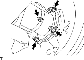
Remove the 4 nuts and rear axle shaft with backing plate.
Note
-
Be careful not to damage the rear axle shaft oil seal.
-
Be careful not to damage the skid control rotor rear.
-
-
-
REMOVE REAR AXLE SHAFT WITH BACKING PLATE RH
Tech Tips
Removal procedure of the RH side is the same as that of the LH side.
-
REMOVE BEARING RETAINER O-RINGS
-
Remove the bearing retainer O-ring from the rear axle housing assembly.
-
-
REMOVE REAR AXLE SHAFT LH OIL SEAL
-
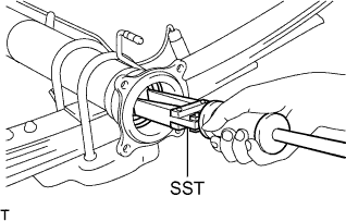
Using SST, remove the rear axle shaft oil seal from the rear axle housing assembly.
- SST
- 09308-00010
-
-
REMOVE REAR AXLE SHAFT RH OIL SEAL
Tech Tips
Removal procedure of the RH side is the same as that of the LH side.
-
REMOVE PROPELLER SHAFT ASSEMBLY (for Super Long Wheelbase)
-
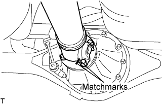
Put matchmarks on both flanges.
-
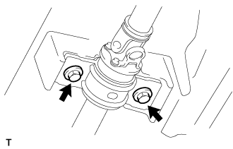
Remove the 4 nuts, bolts and washers.
Tech Tips
If the flange connection is hard to separate, temporarily tighten one nut only and evenly tap the flange with a brass bar and hammer to separate the propeller with center bearing shaft assembly from the differential companion flange.
-
Remove the 2 bolts and center support bearing assembly No.1.
-
Remove the propeller with center bearing shaft assembly.
-
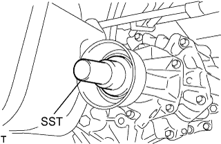
Insert SST in the transmission to prevent oil leakage.
Note
Do not damage the oil seal.
-
Use the following SST for the automatic transmission.
- SST
- 09325-40010
-
Use the following SST for the manual transmission.
- SST
- 09325-20010
-
-
-
REMOVE PROPELLER SHAFT ASSEMBLY (for Long Wheelbase)
-
Put matchmarks on both flanges.
-
Remove the 4 nuts, bolts and washers.
Tech Tips
If the flange connection is hard to separate, temporarily tighten one nut only and evenly tap the flange with a brass bar and hammer to separate the propeller shaft assembly from the differential companion flange.
-
Remove the propeller shaft assembly.
-
Insert SST in the transmission to prevent oil leakage.
Note
Do not damage the oil seal.
-
Use the following SST for the automatic transmission
- SST
- 09325-40010
-
Use the following SST for the manual transmission
- SST
- 09325-20010
-
-
-
DISCONNECT LOAD SENSING BRACKET
-
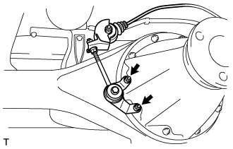
Remove the 2 nuts and load sensing bracket.
-
-
REMOVE REAR DIFFERENTIAL CARRIER ASSEMBLY
-
Support the differential carrier assembly with a jack.
Note
Do not drop the differential carrier assembly
-
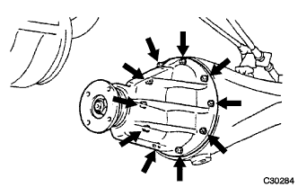
Remove the 10 nuts, washers and differential carrier assembly.
Note
-
Do not damage the installation surface when removing the differential carrier assembly.
-
The remaining oil may leak out when removing the differential carrier assembly.
-
-
-
REMOVE REAR DIFFERENTIAL CARRIER GASKET