PROPELLER SHAFT ASSEMBLY (for Super Long Wheelbase) DISASSEMBLY

-
REMOVE PROPELLER SHAFT ASSEMBLY
-
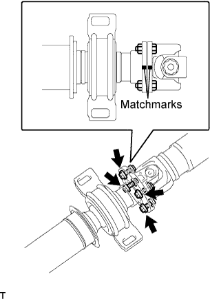
Put matchmarks on both flanges.
-
Remove the 4 nuts, bolts, washers and propeller shaft assembly.
-
-
REMOVE CENTER SUPPORT BEARING ASSEMBLY NO.1
-
Hold the intermediate shaft assembly in a vise between aluminium plates.
Note
Do not overtighten the vise.
-
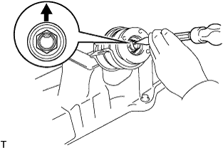
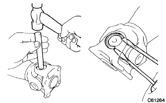
Using a chisel and a hammer, release the staked part of the nut.
Note
Release the staked part of the nut completely, otherwise the threads of the intermediate shaft may be damaged.
-
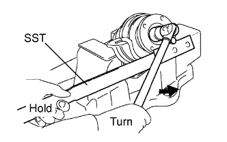
Using SST to hold the universal joint flange, remove the nut and intermediate shaft washer.
- SST
- 09330-00021
-
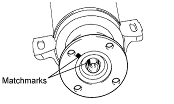
Put matchmarks on the intermediate shaft assembly and universal joint flange.
-
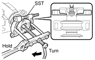
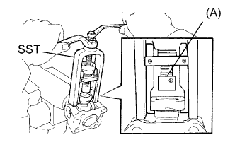
Using SST, remove the universal joint flange from the intermediate shaft assembly.
- SST
- 09950-00020
- 09950-00030
Note
Apply grease to the threads and tip of the SST center bolt before use.
-
Remove the center support bearing assembly No.1 and washer from the intermediate shaft assembly.
-
-
INSPECT PROPELLER SHAFT ASSEMBLY
-
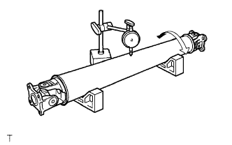
Using a dial indicator, inspect the runout of the propeller shaft.
Maximum runout 0.3 mm (0.0118 in.) Tech Tips
The dial indicator must be set at a right angle to the center of the propeller shaft.
If the shaft runout exceeds the maximum, replace the propeller shaft.
-
-
INSPECT INTERMEDIATE SHAFT
-
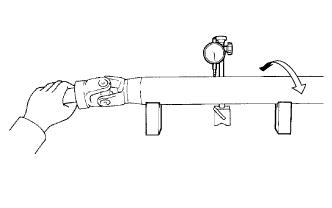
Using a dial indicator, inspect the runout of the intermediate shaft.
Maximum runout 0.3 mm (0.0118 in.) Tech Tips
The dial indicator must be set at a right angle to the center of the propeller shaft.
If the shaft runout exceeds the maximum, replace the propeller shaft.
-
-
REMOVE UNIVERSAL JOINT SPIDER ASSEMBLY
-
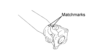
Put matchmarks on the flange yoke and propeller shaft assembly.
-
Using a brass bar and a hammer, slightly tap in the spider bearing outer races.
-
Using 2 screwdrivers, remove the 4 snap rings from the grooves.
-
Hold the propeller shaft assembly in a vise between aluminium plates.
Note
Do not overtighten the vise.
-
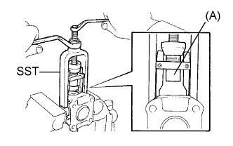
Using SST, push out the spider bearing from the propeller shaft.
- SST
- 09332-25010
Note
Sufficiently raise the part indicated by (A) so that it does not come into contact with the spider bearing.
-
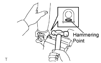
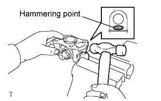
Clamp the spider bearing outer race in a vise between aluminium plates and tap off the propeller shaft with a hammer.
Note
-
Do not overtighten the vise.
-
Do not tap the shaft.
Tech Tips
Remove the spider bearing on the opposite side using the same procedure.
-
-
Install the 2 removed spider bearing outer races to the spider.
-
Hold the flange yoke in a vise between aluminium plates.
Note
Do not overtighten the vise.
-
Using SST, push out the spider bearing from the yoke.
- SST
- 09332-25010
Tech Tips
Sufficiently raise the part indicated by (A) so that it does not come into contact with the spider bearing.
-
Clamp the spider bearing outer race in a vise between aluminium plates and tap off the propeller shaft with a hammer.
Note
Do not overtighten the vise.
-
Remove the spider.
Note
Do not damage the flange yoke.
Tech Tips
Remove the spider bearing on the opposite side using the same procedure.
-