AUTOMATIC TRANSMISSION UNIT (for 1TR-FE, 2TR-FE) DISASSEMBLY

-
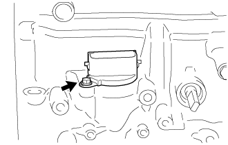
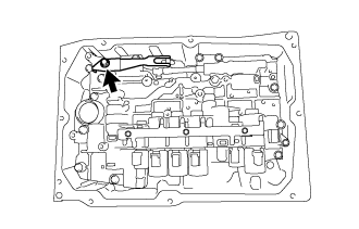
REMOVE BREATHER PLUG HOSE
-
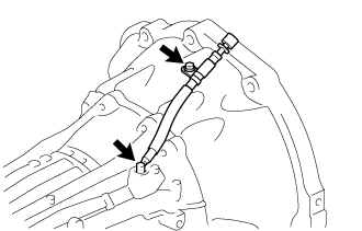
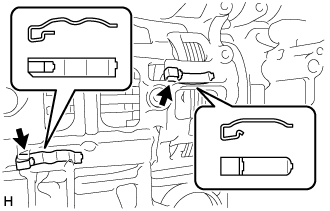
Remove the bolt and breather plug hose from the automatic transmission case sub-assembly.
-
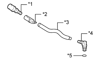
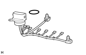
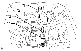
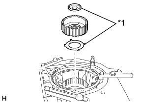
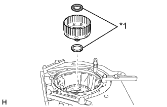
Text in Illustration *1 Breather Plug Sub-assembly *2 Clamp *3 Breather Plug Hose *4 Breather Plug *5 O-ring Remove the O-ring from the breather plug.
-
Remove the breather plug sub-assembly, clamp and breather plug from the breather plug hose.
-
-
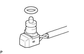
REMOVE TRANSMISSION REVOLUTION SENSOR
-
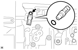
Remove the bolt and transmission revolution sensor NT from the automatic transmission case sub-assembly.
-
Remove the O-ring from the transmission revolution sensor NT.
-
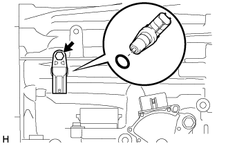
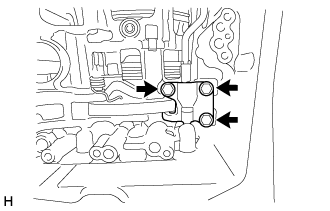
Remove the bolt and transmission revolution sensor SP2 from the automatic transmission case sub-assembly.
-
Remove the O-ring from the transmission revolution sensor SP2.
-
-
REMOVE TRANSMISSION CONTROL SHAFT LEVER LH
-
Remove the nut, spring washer and transmission control shaft lever LH from the park/neutral position switch assembly.
-
-
REMOVE PARK/NEUTRAL POSITION SWITCH ASSEMBLY
-
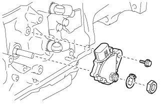
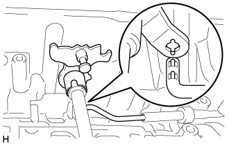
Using a screwdriver, bend the tabs of the lock washer.
-
Remove the nut and the lock washer.
-
Remove the bolt and park/neutral position switch assembly from the automatic transmission case sub-assembly.
Tech Tips
Make sure that the manual valve lever shaft has not been rotated prior to installing the park/neutral position switch assembly as the detent spring may become detached from the manual valve lever shaft.
-
-
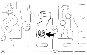
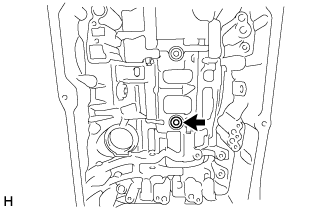
REMOVE REFILL PLUG
-
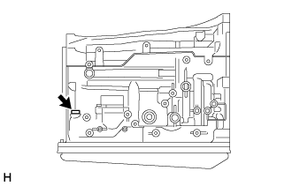
Remove the refill plug from the extension housing sub-assembly.
-
Remove the O-ring from the refill plug.
-
-
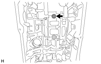
REMOVE AUTOMATIC TRANSMISSION CASE PLUG
-
Remove the 6 automatic transmission case plugs from the automatic transmission case sub-assembly.
-
Remove the 6 O-rings from the 6 automatic transmission case plugs.
-
Using a T55 "TORX" socket wrench, remove the automatic transmission case plug from the automatic transmission case sub-assembly.
-
Remove the O-ring from the automatic transmission case plug.
-
-
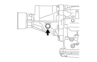
REMOVE OIL COOLER TUBE UNION
-

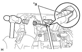
Text in Illustration *a Turn *b Hold Remove the 2 oil cooler tube unions from the automatic transmission case sub-assembly.
-
Remove the 2 O-rings from the 2 oil cooler tube unions.
-
-
REMOVE EXTENSION HOUSING DUST DEFLECTOR
-
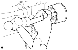
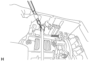
Using a brass bar and hammer, tap out the extension housing dust deflector from the extension housing sub-assembly.
Note
Be careful not to damage the extension housing sub-assembly.
-
-
REMOVE EXTENSION HOUSING SUB-ASSEMBLY
-
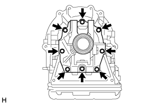
Remove the 8 bolts and extension housing sub-assembly from the automatic transmission case sub-assembly.
Tech Tips
Use a brass bar and hammer to remove the extension housing sub-assembly.
-
-
REMOVE AUTOMATIC TRANSMISSION EXTENSION HOUSING OIL SEAL
-
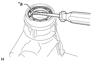
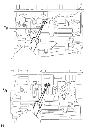
Text in Illustration *a Protective Tape Using a screwdriver, pry out the automatic transmission extension housing oil seal from the extension housing sub-assembly.
Note
Be careful not to damage the extension housing sub-assembly.
Tech Tips
Tape the screwdriver tip before use.
-
-
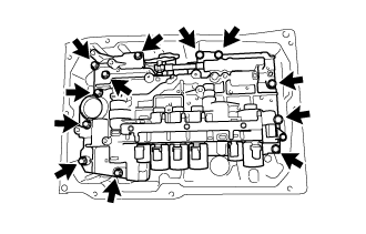
REMOVE AUTOMATIC TRANSMISSION HOUSING
-
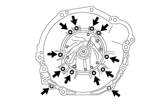
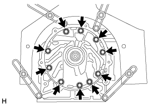
Remove the 12 bolts and automatic transmission housing from the automatic transmission case sub-assembly.
-
-
SECURE AUTOMATIC TRANSMISSION CASE SUB-ASSEMBLY
-
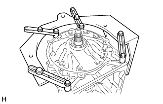
Install the automatic transmission case sub-assembly to an overhaul attachment.
-
-
REMOVE AUTOMATIC TRANSMISSION OIL PAN SUB-ASSEMBLY
Note
Do not turn the transmission over as this will contaminate the transmission valve body assembly with foreign matter located at the bottom of the automatic transmission oil pan sub-assembly.
-
Using a 5 mm socket hexagon wrench, remove the overflow plug and gasket.
-
Remove the drain plug and gasket.
-
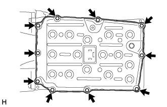
Remove the 10 bolts, automatic transmission oil pan sub-assembly and automatic transmission oil pan gasket.
-
Remove the 4 transmission oil cleaner magnets from the automatic transmission oil pan sub-assembly.
-
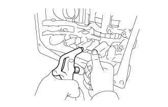
Examine the particles in the automatic transmission oil pan sub-assembly.
-
Collect any steel chips with the removed transmission oil cleaner magnets. Carefully inspect the foreign matter and particles in the automatic transmission oil pan sub-assembly and on the transmission oil cleaner magnets to anticipate the type of wear you will find in the automatic transmission assembly.
Steel (magnetic): bearing, gear and clutch plate wear
Brass (non-magnetic): bush wear
-
-
-
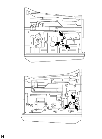
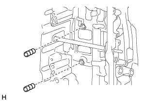
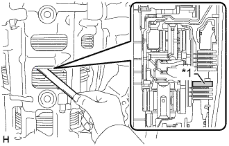
REMOVE TRANSMISSION WIRE
-
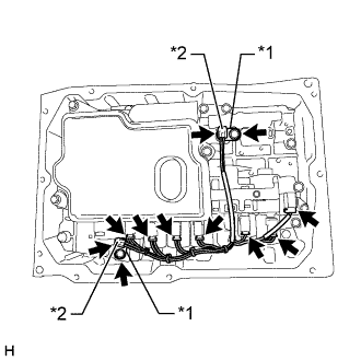
Text in Illustration *1 Temperature Sensor Clamp *2 Temperature Sensor Remove the 2 bolts and 2 temperature sensor clamps, and disconnect the 2 temperature sensors.
-
Disconnect the 7 solenoid valve connectors and transmission wire from the transmission valve body assembly.
-
Remove the bolt and pull out the transmission wire from the automatic transmission case sub-assembly.
-
Remove the O-ring from the connector of transmission wire.
-
Remove the 2 O-rings from the 2 temperature sensors
-
-
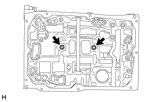
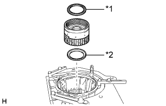
REMOVE VALVE BODY OIL STRAINER ASSEMBLY
-
Remove the 3 bolts and valve body oil strainer assembly from the transmission valve body assembly.
-
Remove the O-ring from the valve body oil strainer assembly.
-
-
REMOVE TRANSMISSION VALVE BODY ASSEMBLY
-
Remove the bolt, detent spring cover and detent spring from the transmission valve body assembly.
-
Remove the 12 bolts and transmission valve body assembly from the automatic transmission case sub-assembly.
-
-
REMOVE TRANSMISSION CASE GASKET
-
Remove the 2 transmission case gaskets from the automatic transmission case sub-assembly.
-
-
REMOVE BRAKE DRUM GASKET
-
Remove the 2 brake drum gaskets from the automatic transmission case sub-assembly.
-
-
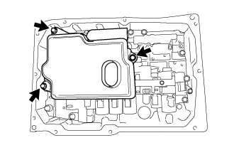
REMOVE PARKING LOCK PAWL BRACKET
-
Remove the 3 bolts and parking lock pawl bracket from the automatic transmission case sub-assembly.
-
-
REMOVE PARKING LOCK ROD SUB-ASSEMBLY
-
Remove the parking lock rod sub-assembly from the manual valve lever sub-assembly.
-
-
REMOVE PARKING LOCK PAWL SHAFT
-
Text in Illustration *1 Parking Lock Pawl *2 E-ring *3 Parking Lock Pawl Shaft *4 Spring Pull out the parking lock pawl shaft from the front side, and remove the parking lock pawl and spring.
-
Remove the E-ring from the parking lock pawl shaft.
-
-
REMOVE MANUAL VALVE LEVER SUB-ASSEMBLY
-
Text in Illustration *a Protective Tape Using a screwdriver and hammer, cut off the spacer and remove it from the manual valve lever shaft.
Note
Be careful not to damage the manual valve lever shaft.
Tech Tips
Tape the screwdriver tip before use.
-
Using a 3 mm pin punch and hammer, drive out the spring pin.
Tech Tips
Slowly drive out the spring pin so that it does not fall into the automatic transmission case sub-assembly.
-
Pull the manual valve lever shaft out through the case and remove the manual valve lever sub-assembly.
-
-
REMOVE MANUAL VALVE LEVER SHAFT OIL SEAL
-
Text in Illustration *a Protective Tape Using a screwdriver, pry out the 2 manual valve lever shaft oil seals from the automatic transmission case sub-assembly.
Note
Be careful not to damage the automatic transmission case sub-assembly.
Tech Tips
Tape the screwdriver tip before use.
-
-
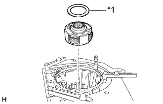
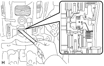
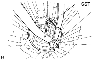
REMOVE OIL PUMP ASSEMBLY
-
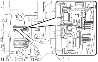
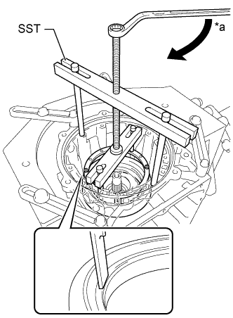
Remove the 10 bolts.
-
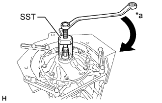
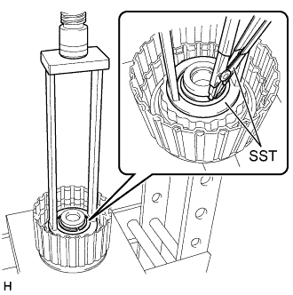
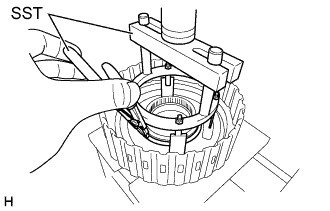
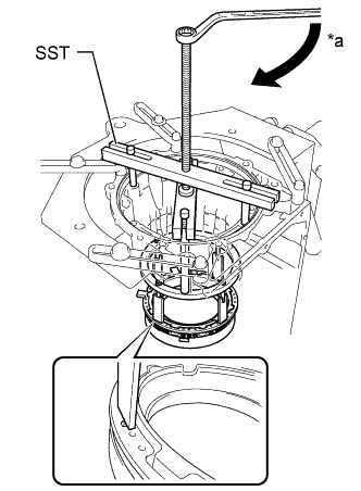
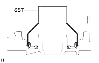
Text in Illustration *a Turn Using SST, pull out the oil pump assembly from the automatic transmission case sub-assembly.
- SST
- 09610-20012
-
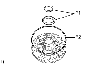
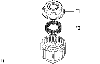
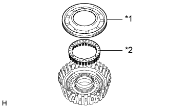
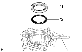
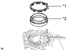
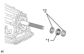
Text in Illustration *1 Thrust Bearing Race *2 Oil Pump O-ring Remove the 2 thrust bearing races from the oil pump assembly.
-
Remove the oil pump O-ring from the oil pump assembly.
-
-
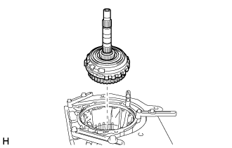
REMOVE CLUTCH DRUM AND INPUT SHAFT ASSEMBLY
-
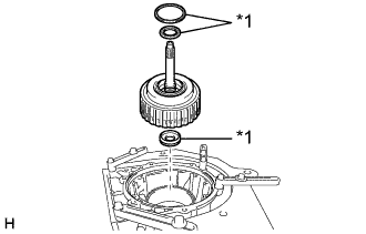
Text in Illustration *1 Thrust Needle Roller Bearing Remove the clutch drum and input shaft assembly from the automatic transmission case sub-assembly.
-
Remove the 3 thrust needle roller bearings from the clutch drum and input shaft assembly.
-
-
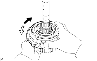
REMOVE DIRECT CLUTCH DRUM SUB-ASSEMBLY
-
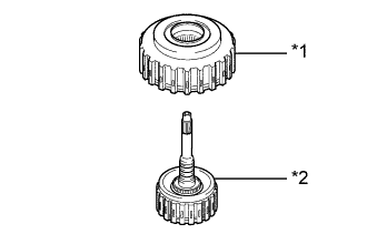
Text in Illustration *1 Direct Clutch Drum Sub-assembly *2 Input Shaft Sub-assembly Remove the direct clutch drum sub-assembly from the input shaft sub-assembly.
-
-
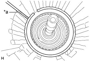
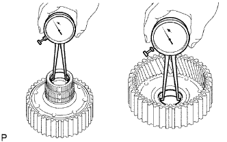
INSPECT CLEARANCE OF NO. 1 CLUTCH (FORWARD CLUTCH)
-
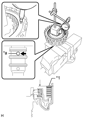
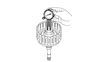
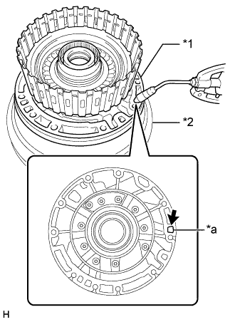
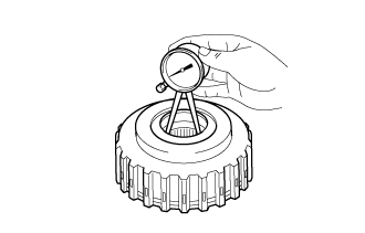
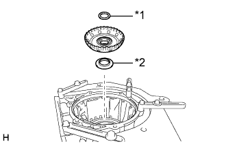
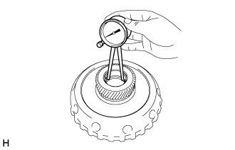
Text in Illustration *1 Selected Forward Clutch Flange *a Oil Hole Using a dial indicator, measure the clearance of the No. 1 clutch at several points while applying compressed air (196 kPa, 2.0 kgf/cm2, 28 psi) to the oil hole as shown in the illustration, and calculate the average.
Standard clearance 0.75 to 1.05 mm (0.0295 to 0.0413 in.) If the clearance is not as specified, select and install an appropriate forward clutch flange that will bring the clearance within the specified range.
Tech Tips
There are forward clutch flanges of different thicknesses.
Forward Clutch Flange Thickness Part No. Thickness (mm (in.)) 35635-71010 3.0 (0.118) 35635-71020 3.1 (0.122) 35635-71030 3.2 (0.126) 35635-71040 3.3 (0.130) 35635-71050 3.4 (0.134) 35635-71060 3.5 (0.138) 35635-71070 3.6 (0.142) 35635-71080 3.7 (0.146) 35635-71090 3.8 (0.150) 35635-71100 3.9 (0.154) 35635-71110 4.0 (0.157) 35635-71120 4.1 (0.161) 35635-71130 4.2 (0.165)
-
-
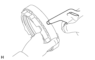
REMOVE CLUTCH DRUM OIL SEAL RING
-
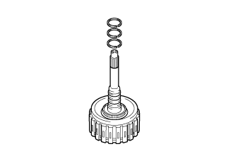
Remove the 3 clutch drum oil seal rings from the input shaft sub-assembly.
-
-
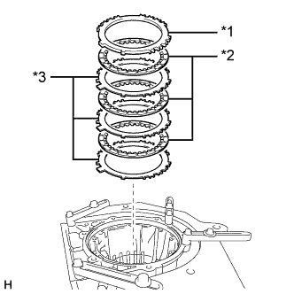
REMOVE NO. 1 CLUTCH DISC (FORWARD CLUTCH DISC)
-
Secure the input shaft sub-assembly in a vise between aluminum plates.
Note
Do not overtighten the vise.
-
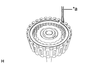
Text in Illustration *a Protective Tape Using a screwdriver, remove the snap ring.
Note
Be careful not to damage the input shaft sub-assembly.
Tech Tips
Tape the screwdriver tip before use.
-
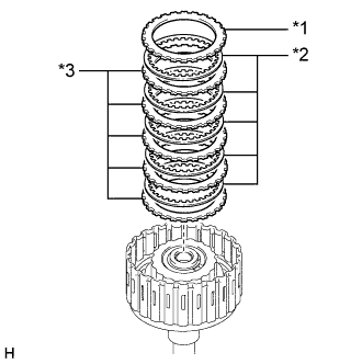
Text in Illustration *1 Forward Clutch Flange *2 No. 1 Clutch Disc *3 No. 1 Clutch Plate Remove the forward clutch flange, 5 No. 1 clutch discs and 5 No. 1 clutch plates from the input shaft sub-assembly.
-
-
INSPECT NO. 1 CLUTCH DISC (FORWARD CLUTCH DISC)
-
Check if the contact surfaces of the No. 1 clutch discs, No. 1 clutch plates and forward clutch flange are worn or burnt.
If necessary, replace them.
Note
-
If the lining of any No. 1 clutch disc is peeled or discolored, or even if part of a groove is damaged, replace all the No. 1 clutch discs.
-
Before installing new No. 1 clutch discs, soak them in ATF for at least 15 minutes.
-
-
-
REMOVE NO. 1 CLUTCH BALANCER
-
Place SST on the No. 1 clutch balancer, and compress the forward clutch return spring sub-assembly with a press.
- SST
- 09387-00110
-
Using SST, remove the snap ring.
- SST
- 09350-30020 ( 09350-07070 )
-
Text in Illustration *1 No. 1 Clutch Balancer *2 Forward Clutch Return Spring Sub-assembly Remove the No. 1 clutch balancer and forward clutch return spring sub-assembly from the input shaft sub-assembly.
-
Remove the O-ring from the No. 1 clutch balancer.
-
-
INSPECT FORWARD CLUTCH RETURN SPRING SUB-ASSEMBLY
-
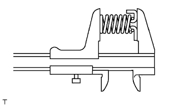
Using a vernier caliper, measure the free length of the forward clutch return spring sub-assembly including the spring seat.
Standard free length 26.74 mm (1.053 in.) If the free length is more than the standard free length, replace the forward clutch return spring sub-assembly.
-
-
REMOVE FORWARD CLUTCH PISTON
-
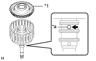
Text in Illustration *1 Forward Clutch Piston *a Oil Hole While holding the forward clutch piston, apply compressed air to the oil hole of the input shaft sub-assembly to remove the forward clutch piston from the input shaft sub-assembly.
-
Remove the O-ring from the forward clutch piston.
-
Remove the O-ring from the input shaft sub-assembly.
-
-
INSPECT INPUT SHAFT SUB-ASSEMBLY
-
Using a caliper gauge, measure the inside diameter of the input shaft sub-assembly bushing.
Standard inside diameter 20.000 to 20.025 mm (0.7874 to 0.7883 in.) If the inside diameter is not as specified, replace the input shaft sub-assembly.
-
-
INSPECT CLEARANCE OF NO. 2 CLUTCH (DIRECT CLUTCH)
-
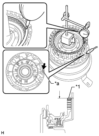
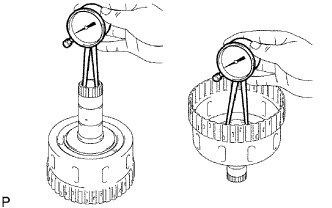
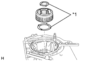
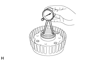
Text in Illustration *1 Selected Direct Clutch Flange *a Oil Hole Using a dial indicator, measure the clearance of the No. 2 clutch at several points while applying compressed air (196 kPa, 2.0 kgf/cm2, 28 psi) to the oil hole as shown in the illustration, and calculate the average.
Standard clearance 0.4 to 0.7 mm (0.0157 to 0.0275 in.) If the clearance is not as specified, select and install an appropriate direct clutch flange that will bring the clearance within the specified range.
Tech Tips
There are direct clutch flanges of different thicknesses.
Direct Clutch Flange Thickness Part No. Thickness (mm (in.)) 35675-71010 3.0 (0.118) 35675-71020 3.1 (0.122) 35675-71030 3.2 (0.126) 35675-71040 3.3 (0.130) 35675-71050 3.4 (0.134) 35675-71060 3.5 (0.138) 35675-71070 3.6 (0.142) 35675-71080 3.7 (0.146) 35675-71090 3.8 (0.150)
-
-
REMOVE NO. 2 CLUTCH DISC (DIRECT CLUTCH DISC)
-
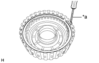
Text in Illustration *a Protective Tape Using a screwdriver, remove the snap ring from the direct clutch drum sub-assembly.
Note
Be careful not to damage the direct clutch drum sub-assembly.
Tech Tips
Tape the screwdriver tip before use.
-
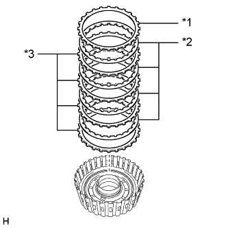
Text in Illustration *1 Direct Clutch Flange *2 No. 2 Clutch Disc *3 No. 2 Clutch Plate Remove the direct clutch flange, 4 No. 2 clutch discs and 4 No. 2 clutch plates from the direct clutch drum sub-assembly.
-
-
INSPECT NO. 2 CLUTCH DISC (DIRECT CLUTCH DISC)
-
Check if the contact surfaces of the No. 2 clutch discs, No. 2 clutch plates and direct clutch flange are worn or burnt.
If necessary, replace them.
Note
-
If the lining of any No. 2 clutch disc is peeled or discolored, or even if part of a groove is damaged, replace all the No. 2 clutch discs.
-
Before installing new No. 2 clutch discs, soak them in ATF for at least 15 minutes.
-
-
-
REMOVE NO. 2 CLUTCH BALANCER
-
Place SST on the No. 2 clutch balancer, and compress the direct clutch return spring sub-assembly with a press.
- SST
- 09380-60011 ( 09381-06030, 09381-06040, 09381-06080, 09381-06100, 09381-06110 )
-
Using SST, remove the snap ring.
- SST
- 09350-30020 ( 09350-07070 )
-
Text in Illustration *1 No. 2 Clutch Balancer *2 Direct Clutch Return Spring Sub-assembly Remove the No. 2 clutch balancer and direct clutch return spring sub-assembly from the direct clutch drum sub-assembly.
-
Remove the O-ring from the No. 2 clutch balancer.
-
-
INSPECT DIRECT CLUTCH RETURN SPRING SUB-ASSEMBLY
-
Using a vernier caliper, measure the free length of the direct clutch return spring sub-assembly including the spring seat.
Standard free length 22.14 mm (0.872 in.) If the free length is more than the standard free length, replace the direct clutch return spring sub-assembly.
-
-
REMOVE DIRECT CLUTCH PISTON
-
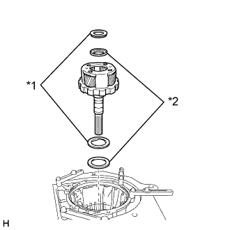
Text in Illustration *1 Oil Pump Assembly *2 Torque Converter Assembly *a Oil Hole Place the oil pump assembly onto the torque converter assembly, and then place the direct clutch drum sub-assembly onto the oil pump assembly.
-
While holding the direct clutch piston, apply compressed air to the oil hole of the oil pump assembly to remove the direct clutch piston from the direct clutch drum sub-assembly.
-
Remove the 2 O-rings from the direct clutch piston.
-
-
INSPECT DIRECT CLUTCH DRUM SUB-ASSEMBLY
-
Using a caliper gauge, measure the inside diameter of the direct clutch drum sub-assembly bushing.
Standard inside diameter 59.515 to 59.540 mm (2.3431 to 2.3440 in.) If the inside diameter is not as specified, replace the direct clutch drum sub-assembly.
-
-
REMOVE MULTIPLE DISC CLUTCH HUB
-
Text in Illustration *1 Thrust Bearing Race Remove the multiple disc clutch hub from the automatic transmission case sub-assembly.
-
Remove the 2 thrust bearing races from the multiple disc clutch hub.
-
-
REMOVE FORWARD CLUTCH HUB SUB-ASSEMBLY
-
Text in Illustration *1 Thrust Needle Roller Bearing Remove the forward clutch hub sub-assembly from the automatic transmission case sub-assembly.
-
Remove the 2 thrust needle roller bearings from the forward clutch hub sub-assembly.
-
-
INSPECT FORWARD CLUTCH HUB SUB-ASSEMBLY
-
Using a caliper gauge, measure the inside diameter of the forward clutch hub sub-assembly bushing.
Standard inside diameter 26.037 to 26.062 mm (1.02508 to 1.02606 in.) If the inside diameter is not as specified, replace the forward clutch hub sub-assembly.
-
-
REMOVE SUN GEAR INPUT DRUM SUB-ASSEMBLY
-
Text in Illustration *1 Thrust Bearing Race *2 Thrust Needle Roller Bearing Remove the sun gear input drum sub-assembly from the automatic transmission case sub-assembly.
-
Remove the thrust needle roller bearing and thrust bearing race from the sun gear input drum sub-assembly.
-
-
INSPECT SUN GEAR INPUT DRUM SUB-ASSEMBLY
-
Using a caliper gauge, measure the inside diameter of the sun gear input drum sub-assembly bushing.
Standard inside diameter 35.811 to 35.835 mm (1.4099 to 1.4108 in.) If the inside diameter is not as specified, replace the sun gear input drum sub-assembly.
-
-
REMOVE FRONT PLANETARY GEAR ASSEMBLY
-
Text in Illustration *1 Thrust Bearing Race Remove the front planetary gear assembly from the automatic transmission case sub-assembly.
-
Remove the 2 thrust bearing races from the front planetary gear assembly
-
-
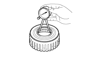
INSPECT FRONT PLANETARY GEAR ASSEMBLY
-
Using a caliper gauge, measure the inside diameter of the front planetary gear assembly bushing.
Standard inside diameter 35.811 to 35.835 mm (1.4099 to 1.4108 in.) If the inside diameter is not as specified, replace the front planetary gear assembly.
-
-
REMOVE FRONT PLANETARY RING GEAR WITH FRONT PLANETARY RING GEAR FLANGE SUB-ASSEMBLY
-
Text in Illustration *1 Thrust Needle Roller Bearing *2 Thrust Bearing Race Remove the front planetary ring gear with front planetary ring gear flange sub-assembly from the automatic transmission case sub-assembly.
-
Remove the thrust needle roller bearing and thrust bearing race from the front planetary ring gear with front planetary ring gear flange sub-assembly.
-
-
REMOVE FRONT PLANETARY RING GEAR FLANGE SUB-ASSEMBLY
-
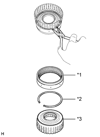
Text in Illustration *1 Front Planetary Ring Gear *2 Snap Ring *3 Front Planetary Ring Gear Flange Sub-assembly Using needle-nose pliers, remove the snap ring and front planetary ring gear flange sub-assembly from the front planetary ring gear.
-
-
INSPECT FRONT PLANETARY RING GEAR FLANGE SUB-ASSEMBLY
-
Using a caliper gauge, measure the inside diameter of the front planetary ring gear flange sub-assembly bushing.
Standard inside diameter 54.038 to 54.063 mm (2.1275 to 2.1284 in.) If the inside diameter is not as specified, replace the front planetary ring gear flange sub-assembly.
-
-
INSPECT CLEARANCE OF NO. 2 BRAKE
-
Make sure that the No. 2 brake piston moves smoothly when applying and releasing compressed air (392 kPa, 4.0 kgf/cm2, 57 psi).
-
Text in Illustration *1 Selected No. 2 Brake Flange Using a feeler gauge, measure the No. 2 brake pack clearance between the No. 2 brake disc and No. 2 brake flange.
Standard clearance 0.4 to 0.7 mm (0.0158 to 0.0275 in.) If the clearance is not as specified, select and install an appropriate No. 2 brake flange that will bring the clearance within the specified range.
No. 2 Brake Flange Thickness Mark Thickness (mm (in.)) 0 2.0 (0.0787) 1 2.1 (0.0827) 2 2.2 (0.0866) 3 2.3 (0.0906) 4 2.4 (0.0945) 5 2.5 (0.0984) 6 2.6 (0.102) 7 2.7 (0.106) 8 2.8 (0.110)
-
-
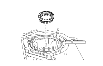
REMOVE NO. 2 BRAKE CYLINDER WITH NO.2 BRAKE PISTON
-
Text in Illustration *a Turn Place SST on the No. 2 brake cylinder, and compress the No. 2 brake piston return spring sub-assembly with a press.
- SST
- 09380-60011 ( 09381-06010, 09381-06020, 09381-06040, 09381-06050, 09381-06060, 09381-06090, 09381-06100, 09381-06110, 09381-06120 )
-
Using a screwdriver, remove the snap ring from the automatic transmission case sub-assembly.
Note
Be careful not to damage the automatic transmission case sub-assembly.
Tech Tips
Tape the screwdriver tip before use.
-
Text in Illustration *1 No. 2 Brake Cylinder with No. 2 Brake Piston *2 No. 2 Brake Piston Return Spring Sub-assembly Remove the No. 2 brake cylinder with No. 2 brake piston and No. 2 brake piston return spring sub-assembly from the automatic transmission case sub-assembly.
-
-
INSPECT NO. 2 BRAKE PISTON RETURN SPRING SUB-ASSEMBLY
-
Using a vernier caliper, measure the free length of the No. 2 brake piston return spring sub-assembly including the spring seat.
Standard free length 16.68 mm (0.657 in.) If the free length is more than the standard free length, replace the No. 2 brake piston return spring sub-assembly.
-
-
REMOVE NO. 2 BRAKE PISTON
-
While holding the No. 2 brake piston, apply compressed air to the oil hole of the No. 2 brake cylinder to remove the No. 2 brake piston from the No. 2 brake cylinder.
-
Remove the 2 O-rings from the No. 2 brake piston
-
-
REMOVE NO. 2 BRAKE DISC
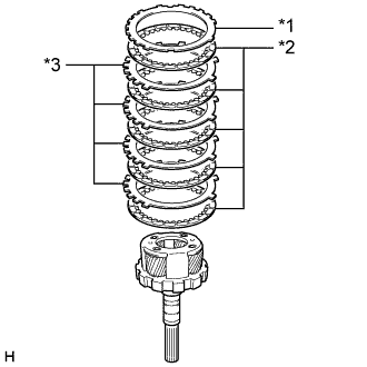
-
Text in Illustration *1 No. 2 Brake Flange *2 No. 2 Brake Disc *3 No. 2 Brake Plate Remove the 2 No. 2 brake flanges, 4 No. 2 brake discs and 3 No. 2 brake plates from the automatic transmission case sub-assembly.
-
-
INSPECT NO. 2 BRAKE DISC
-
Check if the contact surfaces of the No. 2 brake discs, No. 2 brake plates and No. 2 brake flanges are worn or burnt.
If necessary, replace them.
Note
-
If the lining of any No. 2 brake disc is peeled or discolored, or even if part of a groove is damaged, replace all the No. 2 brake discs.
-
Before installing new No. 2 brake discs, soak them in ATF for at least 15 minutes.
-
-
-
REMOVE CENTER PLANETARY RING GEAR FLANGE WITH CENTER PLANETARY RING GEAR
-
Text in Illustration *1 Thrust Needle Roller Bearing Remove the center planetary ring gear flange with center planetary ring gear from the automatic transmission case sub-assembly.
-
Remove the 2 thrust needle roller bearings from the center planetary ring gear flange with center planetary ring gear.
-
-
REMOVE CENTER PLANETARY RING GEAR
-
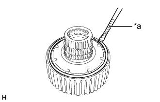
Text in Illustration *a Protective Tape Using a screwdriver, remove the snap ring from the center planetary ring gear flange with center planetary ring gear.
Note
Be careful not to damage the center planetary ring gear flange with center planetary ring gear.
Tech Tips
Tape the screwdriver tip before use.
-
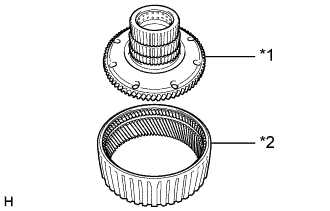
Text in Illustration *1 Center Planetary Ring Gear Flange *2 Center Planetary Ring Gear Remove the center planetary ring gear from the center planetary ring gear flange.
-
-
REMOVE CENTER PLANETARY GEAR ASSEMBLY
-
Text in Illustration *1 Thrust Bearing Race Remove the center planetary gear assembly from the automatic transmission case sub-assembly.
-
Remove the thrust bearing race from the center planetary gear assembly.
-
-
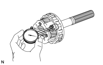
INSPECT CENTER PLANETARY GEAR ASSEMBLY
-
Using a feeler gauge, measure the center planetary gear pinion thrust clearance.
Standard clearance 0.12 to 0.68 mm (0.00473 to 0.0267 in.) If the clearance is not as specified, replace the center planetary gear assembly.
-
-
REMOVE PLANETARY SUN GEAR
-
Remove the planetary sun gear from the automatic transmission case sub-assembly.
-
-
INSPECT CLEARANCE OF NO. 1 BRAKE
-
Make sure that the No. 1 brake piston moves smoothly when applying and releasing compressed air (392 kPa, 4.0 kgf/cm2, 57 psi).
-
Text in Illustration *1 Selected No. 1 Brake Flange Using a feeler gauge, measure the No. 1 brake pack clearance between the No. 1 brake disc and No. 1 brake flange.
Standard clearance 0.3 to 0.6 mm (0.0119 to 0.0236 in.) If the clearance is not as specified, select and install an appropriate No. 1 brake flange that will bring the clearance within the specified range.
No. 1 Brake Flange Thickness Mark Thickness (mm (in.)) 0 4.9 (0.193) 1 5.0 (0.197) 2 5.1 (0.201) 3 5.2 (0.205) 4 5.3 (0.209) 5 5.4 (0.213) 6 5.5 (0.217) 7 5.6 (0.220) 8 5.7 (0.224) A 5.8 (0.228)
-
-
REMOVE NO. 1 BRAKE DISC
-
Text in Illustration *a Protective Tape Using a screwdriver, remove the snap ring from the automatic transmission case sub-assembly.
Note
Be careful not to damage the automatic transmission case sub-assembly.
Tech Tips
Tape the screwdriver tip before use.
-
Text in Illustration *1 No. 1 Brake Flange *2 No. 1 Brake Disc *3 No. 1 Brake Plate Remove the No. 1 brake flange, 3 No. 1 brake discs and 3 No. 1 brake plates from the automatic transmission case sub-assembly.
-
-
INSPECT NO. 1 BRAKE DISC
-
Check if the contact surfaces of the No. 1 brake discs, No. 1 brake plates and No. 1 brake flange are worn or burnt.
If necessary, replace them.
Note
-
If the lining of any No. 1 brake disc is peeled or discolored, or even if part of a groove is damaged, replace all the No. 1 brake discs.
-
Before installing new No. 1 brake discs, soak them in ATF for at least 15 minutes.
-
-
-
REMOVE NO. 1 BRAKE CYLINDER WITH NO. 1 BRAKE PISTON
-
Text in Illustration *a Turn Place SST on the No. 1 brake piston return spring sub-assembly, and compress the No. 1 brake piston return spring sub-assembly with a press.
- SST
- 09380-60011 ( 09381-06010, 09381-06040, 09381-06050, 09381-06070, 09381-06090, 09381-06100, 09381-06110, 09381-06120 )
-
Using a screwdriver, remove the snap ring from the automatic transmission case sub-assembly.
Note
Be careful not to damage the automatic transmission case sub-assembly.
Tech Tips
Tape the screwdriver tip before use.
-
Text in Illustration *1 No. 1 Brake Piston Return Spring Sub-assembly *2 No. 1 Brake Cylinder with No. 1 Brake Piston Remove the No. 1 brake piston return spring sub-assembly and No. 1 brake cylinder with No. 1 brake piston from the automatic transmission case sub-assembly.
-
-
INSPECT NO. 1 BRAKE PISTON RETURN SPRING SUB-ASSEMBLY
-
Using a vernier caliper, measure the free length of the No. 1 brake piston return spring sub-assembly including the spring seat.
Standard free length 16.72 mm (0.658 in.) If the free length is more than the standard free length, replace the No. 1 brake piston return spring sub-assembly.
-
-
REMOVE NO. 1 BRAKE PISTON
-
While holding the No. 1 brake piston, apply compressed air to the oil hole of the No. 1 brake cylinder to remove the No. 1 brake piston from the No. 1 brake cylinder.
-
Remove the 2 O-rings from the No. 1 brake piston
-
-
INSPECT CLEARANCE OF NO. 4 BRAKE
-
Make sure that the 1st and reverse brake piston moves smoothly when applying and releasing compressed air (392 kPa, 4.0 kgf/cm2, 57 psi).
-
Text in Illustration *1 Selected No. 4 Brake Flange Using a feeler gauge, measure the No. 4 brake pack clearance between the No. 4 brake disc and No. 4 brake flange.
Standard clearance 0.5 to 0.8 mm (0.0197 to 0.0314 in.) If the clearance is not as specified, select and install an appropriate No. 4 brake flange that will bring the clearance within the specified range.
No. 4 Brake Flange Thickness Mark Thickness (mm (in.)) 0 1.80 (0.0709) 1 1.97 (0.0776) 3 2.11 (0.0831) 4 2.25 (0.0886) 5 2.39 (0.0941) 7 2.53 (0.0996) 8 2.67 (0.105) 10 2.81 (0.111) 11 2.95 (0.116) 12 3.09 (0.122) 14 3.23 (0.127)
-
-
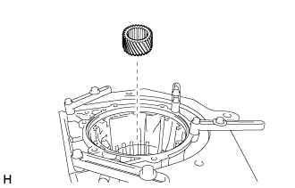
REMOVE INTERMEDIATE SHAFT WITH NO. 3 ONE-WAY CLUTCH ASSEMBLY AND REAR PLANETARY RING GEAR
-
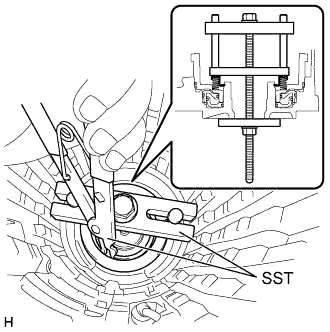
Using SST, remove the snap ring from the automatic transmission case sub-assembly.
- SST
- 09350-30020 ( 09350-07060 )
-
Remove the intermediate shaft with No. 3 one-way clutch assembly and rear planetary ring gear from the automatic transmission case sub-assembly.
-
-
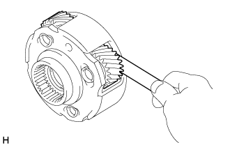
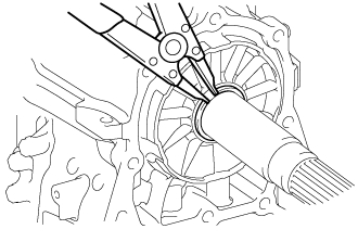
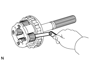
INSPECT NO. 3 ONE-WAY CLUTCH ASSEMBLY
-
Hold the rear planetary ring gear and turn the No. 3 one-way clutch assembly.
Text in Illustration 
Lock 
Free -
Check that the No. 3 one-way clutch assembly turns freely when turned counterclockwise and locks when turned clockwise.
If there is a problem with the No. 3 one-way clutch assembly, replace it.
-
-
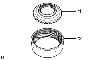
REMOVE NO. 3 ONE-WAY CLUTCH ASSEMBLY WITH ONE-WAY CLUTCH INNER RACE
-
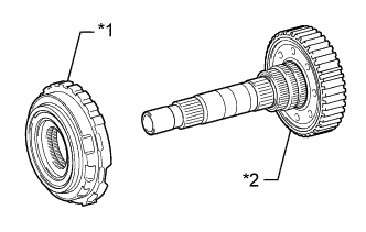
Text in Illustration *1 No. 3 One-way Clutch Assembly with One-way Clutch Inner Race *2 Intermediate Shaft with Rear Planetary Ring gear Remove the No. 3 one-way clutch assembly with one-way clutch inner race from the intermediate shaft with rear planetary ring gear.
-
-
REMOVE ONE-WAY CLUTCH INNER RACE
-
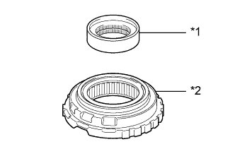
Text in Illustration *1 One-way Clutch Inner Race *2 No. 3 One-way Clutch Assembly Remove the one-way clutch inner race from the No. 3 one-way clutch assembly.
-
-
REMOVE REAR PLANETARY RING GEAR FLANGE SUB-ASSEMBLY WITH REAR PLANETARY RING GEAR
-
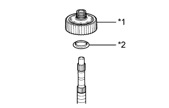
Text in Illustration *1 Rear Planetary Ring Gear Flange Sub-assembly with Rear Planetary Ring Gear *2 Thrust Bearing Race Remove the rear planetary ring gear flange sub-assembly with rear planetary ring gear from the intermediate shaft.
-
Remove the thrust bearing race from the rear planetary ring gear flange sub-assembly with rear planetary ring gear.
-
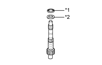
Text in Illustration *1 Thrust Needle Roller Bearing *2 Thrust Bearing Race Remove the thrust needle roller bearing and thrust bearing race from the intermediate shaft.
-
-
INSPECT REAR PLANETARY RING GEAR FLANGE SUB-ASSEMBLY
-
Using a caliper gauge, measure the inside diameter of the rear planetary ring gear flange sub-assembly bushing.
Standard inside diameter 32.176 to 32.201 mm (1.2668 to 1.2677 in.) If the inside diameter is not as specified, replace the rear planetary ring gear flange sub-assembly.
-
-
REMOVE REAR PLANETARY RING GEAR
-
Text in Illustration *a Protective Tape Using a screwdriver, remove the snap ring from the rear planetary ring gear flange sub-assembly with rear planetary ring gear.
Note
Be careful not to damage the rear planetary ring gear flange sub-assembly with rear planetary ring gear.
Tech Tips
Tape the screwdriver tip before use.
-
Text in Illustration *1 Rear Planetary Ring Gear Flange Sub-assembly *2 Rear Planetary Ring Gear Remove the rear planetary ring gear from the rear planetary ring gear flange sub-assembly.
-
-
REMOVE REAR PLANETARY GEAR ASSEMBLY WITH NO. 4 BRAKE DISC
-
Using a snap ring expander, remove the snap ring from the output shaft of the rear planetary gear assembly.
-
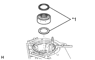
Text in Illustration *1 Thrust Needle Roller Bearing *2 Thrust Bearing Race Remove the 2 thrust bearing races and thrust needle roller bearing from the output shaft of the rear planetary gear assembly.
-
Text in Illustration *1 Thrust Needle Roller Bearing *2 Thrust Bearing Race Remove the rear planetary gear assembly with No. 4 brake disc from the automatic transmission case sub-assembly.
-
Remove the 2 thrust needle roller bearings and 2 thrust bearing races from the rear planetary gear assembly with No. 4 brake disc.
-
Remove the thrust bearing race from the automatic transmission case sub-assembly.
-
-
INSPECT REAR PLANETARY GEAR ASSEMBLY
-
Using a feeler gauge, measure the rear planetary gear pinion thrust clearance.
Standard clearance 0.2 to 0.6 mm (0.00788 to 0.0236 in.) If the clearance is not as specified, replace the rear planetary gear assembly.
-
Using a caliper gauge, measure the inside diameter of the rear planetary gear bushing.
Standard inside diameter 20.000 to 20.025 mm (0.7874 to 0.7883 in.) If the inside diameter is not as specified, replace the rear planetary gear assembly.
-
-
REMOVE NO. 4 BRAKE DISC
-
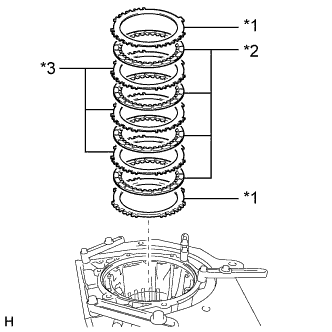
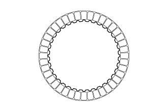
Text in Illustration *1 No. 4 Brake Flange *2 No. 4 Brake Disc *3 No. 4 Brake Plate Remove the No. 4 brake flange, 5 No. 4 brake discs and 4 No. 4 brake plates from the rear planetary gear assembly.
-
Remove the No. 4 brake flange from the automatic transmission case sub-assembly.
-
-
INSPECT NO. 4 BRAKE DISC
-
Check if the contact surfaces of the No. 4 brake discs, No. 4 brake plates and No. 4 brake flanges are worn or burnt.
If necessary, replace them.
Note
-
If the lining of any No. 4 brake disc is peeled or discolored, or even if part of a groove is damaged, replace all the No. 4 brake discs.
-
Before installing new No. 4 brake discs, soak them in ATF for at least 15 minutes.
-
-
-
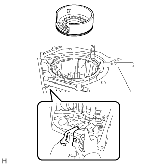
REMOVE 1ST AND REVERSE BRAKE PISTON
-
Place SST on the 1st and reverse brake return spring sub-assembly and compress the 1st and reverse brake return spring sub-assembly.
- SST
- 09380-60011 ( 09381-05040, 09381-05050, 09381-06030, 09381-06040, 09381-06080, 09381-06120, 09381-06130, 09381-06140 )
-
Using SST, remove the snap ring from the automatic transmission case sub-assembly.
- SST
- 09350-30020 ( 09350-07070 )
-
Remove the 1st and reverse brake return spring sub-assembly from the automatic transmission case sub-assembly.
-
Apply compressed air to the oil hole of the automatic transmission case sub-assembly to remove the 1st and reverse brake piston from the automatic transmission case sub-assembly.
-
Remove the O-ring from the 1st and reverse brake piston.
-
-
INSPECT 1ST AND REVERSE BRAKE RETURN SPRING SUB-ASSEMBLY
-
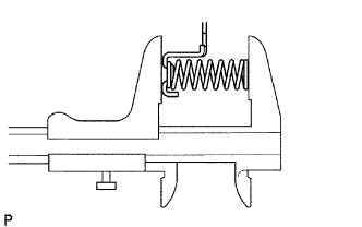
Using a vernier caliper, measure the free length of the 1st and reverse brake return spring sub-assembly including the spring seat.
Standard free length 23.74 mm (0.935 in.) If the free length is more than the standard free length, replace the 1st and reverse return spring sub-assembly.
-
-
REMOVE BRAKE REACTION SLEEVE
-
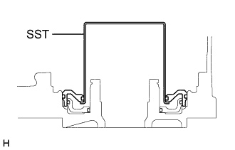
Using SST, remove the brake reaction sleeve from the automatic transmission case sub-assembly.
- SST
- 09350-30020 ( 09350-07080 )
-
Remove the 2 O-rings from the brake reaction sleeve.
-
-
REMOVE NO. 4 BRAKE PISTON
-
Using SST, remove the No. 4 brake piston from the automatic transmission case sub-assembly.
- SST
- 09350-30020 ( 09350-07090 )
-
Remove the 2 O-rings from the No. 4 brake piston.
-
-
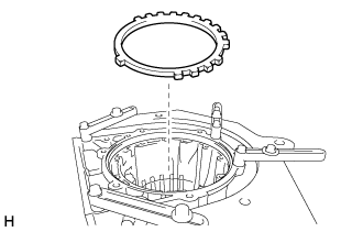
REMOVE BRAKE PLATE STOPPER SPRING
-
Remove the 2 brake plate stopper springs from the automatic transmission case sub-assembly.
-