AUTOMATIC TRANSMISSION ASSEMBLY (for 1GD-FTV) INSTALLATION
-
INSTALL TORQUE CONVERTER CLUTCH ASSEMBLY
-
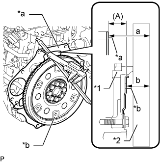
Text in Illustration *1 Flywheel *2 Straightedge *a Engine Assembly Surface *b Drive Plate Surface Using a vernier caliper and straightedge, measure the dimension (A) between the automatic transmission assembly contact surface of the engine assembly and torque converter assembly contact surface of the drive plate and ring gear sub-assembly.
Measurement Method a - b = A -
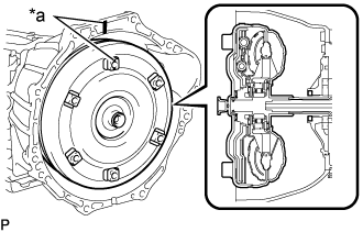
Text in Illustration *a Matchmark Align the matchmark on the automatic transmission case sub-assembly with the one on the torque converter assembly and engage the splines of the input shaft with the turbine runner splines.
Note
Install the torque converter assembly to the input shaft while keeping it horizontal.
-
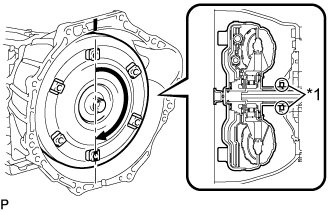
Text in Illustration *1 Front Oil Pump Oil Seal Rotate the torque converter assembly approximately 180° and engage the splines of the stator shaft with the stator assembly.
Note
-
Do not damage the front oil pump oil seal.
-
Install the torque converter assembly to the input shaft while keeping it horizontal.
-
-
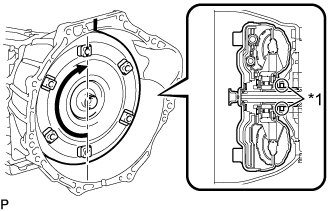
Text in Illustration *1 Front Oil Pump Oil Seal Rotate the torque converter assembly approximately 180° again, align the matchmark on the torque converter assembly with the one on the automatic transmission case sub-assembly and insert the key of the torque converter assembly into the groove of the oil pump drive gear.
Note
-
Do not push the torque converter assembly excessively when rotating it.
-
Do not damage the front oil pump oil seal.
-
Install the torque converter assembly to the input shaft while keeping it horizontal.
-
-
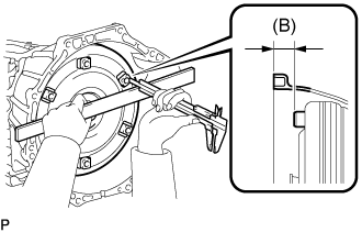
Using a vernier caliper and straightedge, measure the dimension (B) shown in the illustration and check that the dimension (B) is more than the dimension (A), which was measured in the previous step.
Standard A + 1 mm (0.0394 in.) or more Note
-
Make sure to deduct the thickness of the straightedge.
-
If the automatic transmission assembly is installed to the engine assembly with the torque converter assembly not sufficiently inserted, the torque converter assembly may be damaged.
-
-
-
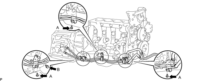
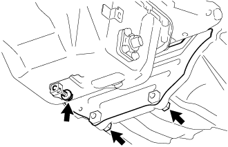
INSTALL WIRING HARNESS CLAMP BRACKET
-
Install the 2 wire harness clamp brackets to the automatic transmission assembly with the 2 bolts.
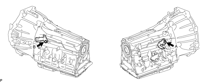
- Torque:
- for bolt A
- 13 N*m { 130 kgf*cm, 9 ft.*lbf }
- for bolt B
- 8.0 N*m { 82 kgf*cm, 71 in.*lbf }
-
-
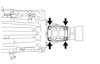
INSTALL REAR ENGINE MOUNTING INSULATOR ASSEMBLY
-
Install the rear engine mounting insulator with the 4 bolts.
- Torque:
- 29 N*m { 296 kgf*cm, 21 ft.*lbf }
-
-
INSTALL AUTOMATIC TRANSMISSION ASSEMBLY
-
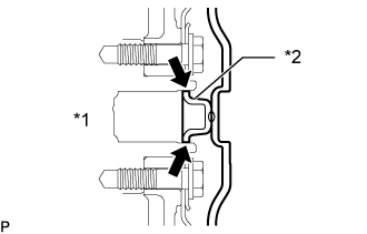
Text in Illustration *1 Crankshaft *2 Torque Converter Assembly Centerpiece 
Clutch Spline Grease Apply clutch spline grease to the circumference of the crankshaft that contacts the torque converter assembly centerpiece.
Clutch spline grease Toyota Genuine Clutch Spline Grease or equivalent Maximum spread About 1 g (0.0353 oz.) -
Confirm that the 2 knock pins are installed on the engine assembly and are not damaged.
-
While keeping the engine assembly and automatic transmission assembly horizontal, align the 2 knock pins with the holes in the automatic transmission assembly and install the 5 bolts.
- Torque:
- 71 N*m { 724 kgf*cm, 52 ft.*lbf }
Note
-
Do not use excessive force when installing the automatic transmission assembly.
-
Check that the torque converter assembly rotates.
-
Make sure that the wire harness or other similar items are not pinched between the contact surfaces.
-
-
CONNECT REAR ENGINE MOUNTING INSULATOR ASSEMBLY
-
Connect the rear engine mounting insulator assembly to the body with the bolt, nut and 2 washers.
- Torque:
- 98 N*m { 999 kgf*cm, 72 ft.*lbf }
-
-
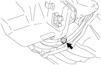
CONNECT GROUND CABLE
-
Connect the ground cable with the bolt.
- Torque:
- 13 N*m { 130 kgf*cm, 9 ft.*lbf }
-
Connect the ground cable clamp.
-
-
CONNECT WIRE HARNESS
-
Connect the 3 wire harness clamps to the automatic transmission assembly.
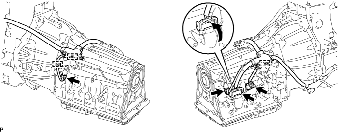
-
Connect the park/neutral position switch connector, transmission wire connector and 2 transmission revolution sensor connectors.
Tech Tips
Push up the lever until the claw of the transmission wire connector makes a connection sound.
-
-
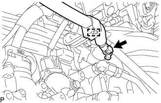
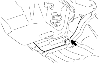
CONNECT OIL COOLER TUBE
-
Connect the ends of the 2 oil cooler tubes to the automatic transmission assembly by hand.
-
Connect the 3 oil cooler tube clamps with the 4 bolts.
- Torque:
- for bolt A
- 8.0 N*m { 82 kgf*cm, 71 in.*lbf }
- for bolt B
- 12 N*m { 122 kgf*cm, 9 ft.*lbf }
-
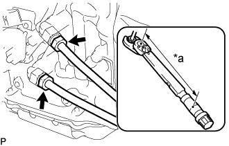
Text in Illustration *a Torque Wrench Fulcrum Length Using a 17 mm union nut wrench, tighten the 2 oil cooler tubes to the automatic transmission assembly
- Torque:
- 34 N*m { 347 kgf*cm, 25 ft.*lbf }
Tech Tips
-
Calculate the torque wrench reading when changing the fulcrum length of the torque wrench.
-
When using a union nut wrench (fulcrum length of 30 mm (1.1811 in.)) + torque wrench (fulcrum length of 180 mm (7.0866 in.)): 29 N*m (297 kgf*cm, 21 ft.*lbf)
-
Connect the wire harness clamp to the oil cooler tube clamp.
-
-
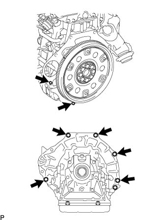
INSTALL DRIVE PLATE AND TORQUE CONVERTER SETTING BOLT
-
Turn the crankshaft to gain access to the installation locations of the 6 drive plate and torque converter setting bolts and install each bolt while holding the crankshaft pulley bolt with a wrench.
- Torque:
- 48 N*m { 489 kgf*cm, 35 ft.*lbf }
Note
Install the black colored bolt first, and then the 5 silver colored bolts.
-
-
INSTALL NO. 2 REAR END PLATE
-
Install the No. 2 rear end plate with the 3 bolts.
- Torque:
- 73 N*m { 744 kgf*cm, 54 ft.*lbf }
-
-
INSTALL NO. 4 CYLINDER BLOCK INSULATOR
-
Install the No. 4 cylinder block insulator.
-
-
INSTALL NO. 1 TRANSMISSION CONTROL CABLE BRACKET
-
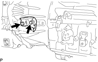
Install the No. 1 transmission control cable bracket to the automatic transmission assembly with the 2 bolts.
- Torque:
- 14 N*m { 143 kgf*cm, 10 ft.*lbf }
-
-
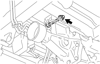
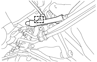
CONNECT TRANSMISSION CONTROL CABLE ASSEMBLY
-
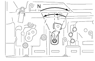
Turn the control shaft lever clockwise until it stops, and then return the control shaft lever counterclockwise 2 notches to N.
-
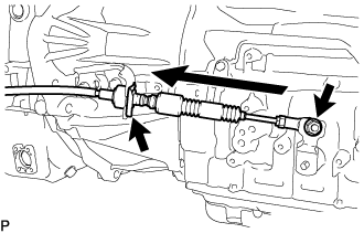
Connect the end of the transmission control cable assembly to the transmission control shaft lever LH.
-
Move the shift lever to N, and with the cable end lightly pushed toward the front of the vehicle, install the transmission control cable assembly to the transmission control shaft lever LH with the nut.
- Torque:
- 15 N*m { 148 kgf*cm, 11 ft.*lbf }
Tech Tips
Tighten the nut with no slack in the control cable.
-
Connect the transmission control cable assembly to the No. 1 transmission control cable bracket with a new clip.
-
-
INSTALL FRONT EXHAUST PIPE ASSEMBLY
-
INSTALL STARTER ASSEMBLY
-
INSTALL PROPELLER SHAFT WITH CENTER BEARING ASSEMBLY
-
ADD AUTOMATIC TRANSMISSION FLUID
-
Fill the transmission with the correct amount of fluid as listed in the table below.
Standard Capacity Performed Repair Engine Type Fill Amount Automatic transmission assembly replacement (when reusing the torque converter assembly) 1TR-FE, 2TR-FE 2.5 liters (2.6 US qts, 2.2 Imp. qts) 1GD-FTV 4.4 liters (4.6 US qts, 3.9 Imp. qts) Removal and installation of the automatic transmission oil pan sub-assembly and drain plug 1TR-FE, 2TR-FE 1.0 liters (1.1 US qts, 0.9 Imp. qts) 1GD-FTV 2.5 liters (2.6 US qts, 2.2 Imp. qts) Removal and installation of the transmission valve body assembly 1TR-FE, 2TR-FE 1.7 liters (1.8 US qts, 1.5 Imp. qts) 1GD-FTV 3.3 liters (3.5 US qts, 2.9 Imp. qts) Torque converter assembly replacement 1TR-FE, 2TR-FE 2.5 liters (2.6 US qts, 2.2 Imp. qts) 1GD-FTV 4.4 liters (4.6 US qts, 3.9 Imp. qts) Tech Tips
If the specified amount of automatic transmission fluid cannot be added, perform the following:
-
Temporarily install the O-ring and refill plug to the automatic transmission assembly.
Tech Tips
Reuse the old O-ring as the refill plug will be removed again to adjust the fluid level.
-
Lower the vehicle.
-
Start the engine.
Note
To reduce load, make sure that all electrical systems, such as the air conditioning, lighting system, electric fan and audio system, are off.
-
Slowly move the shift lever from P to S, then move the shift lever to P.
-
Allow the engine to idle for 30 seconds to warm it up.
-
Turn the ignition switch off.
-
Remove the refill plug and O-ring from the automatic transmission assembly.
-
Fill the automatic transmission assembly with the correct amount of automatic transmission fluid as listed in the table above.
-
Temporarily install the O-ring and refill plug to the automatic transmission assembly.
Tech Tips
Reuse the old O-ring as the refill plug will be removed again to adjust the fluid level.
-
-
-
CONNECT CABLE TO NEGATIVE BATTERY TERMINAL
Note
When disconnecting the cable, some systems need to be initialized after the cable is reconnected Click here.
-
INSPECT SHIFT LEVER POSITION
-
When moving the shift lever from P to R with the ignition switch to ON and the brake pedal depressed, make sure that the shift lever moves smoothly and correctly to P.
-
Make sure that the shifting lever moves smoothly and can be moderately operated.
-
When starting the engine, make sure that the vehicle moves forward when shifting from N to D and moves rearward when shifting to R.
-
-
ADJUST AUTOMATIC TRANSMISSION FLUID
-
INSPECT FOR EXHAUST GAS LEAK
-
If gas is leaking, tighten the areas necessary to stop the leak. Replace damaged parts as necessary.
-
-
INSPECT FOR AUTOMATIC TRANSMISSION FLUID LEAK
-
INSTALL NO. 2 ENGINE UNDER COVER
-
Install the No. 2 engine under cover to the body with the 6 bolts.
- Torque:
- 13 N*m { 133 kgf*cm, 10 ft.*lbf }
-