DIRECT CLUTCH REASSEMBLY

-
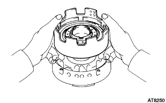
INSTALL DIRECT CLUTCH PISTON SUB-ASSEMBLY
-
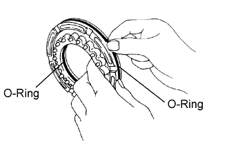
Coat 2 new O-rings with ATF, and install them in the direct clutch piston.
-
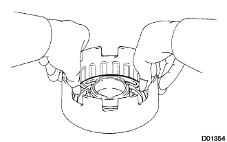
Be careful not to damage the O-rings, and press in the direct clutch piston into the clutch drum with both hands.
-
-
INSTALL DIRECT CLUTCH RETURN SPRING SUB-ASSEMBLY
-
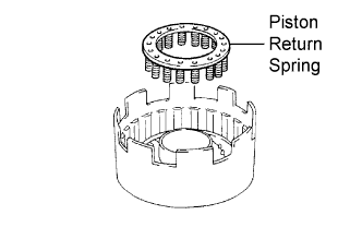
Install the return spring.
-
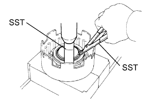
Place SST on the spring retainer, and compress the return spring with a press.
- SST
- 09350-30020 ( 09350-07040 )
-
Using SST, install the snap ring.
- SST
- 09350-30020 ( 09350-07070 )
Note
Be sure the end gap of the snap ring is not aligned with the spring retainer claw.
-
-
INSTALL DIRECT CLUTCH FLANGE
-
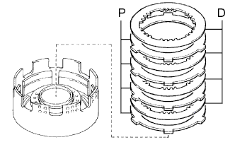
Install the cushion plate.
-
Install the 4 plates and the 4 discs.
Install in order P = Plate, D = Disc P - D - P - D - P - D - P - D -
Install the flange with the flat end facing downward.
-
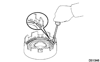
Using a screwdriver, install the snap ring.
Note
Be sure the end gap of the snap ring is not aligned with the cutout portion of the direct clutch drum.
-
-
INSPECT PACK CLEARANCE OF DIRECT CLUTCH
-
Place the direct clutch assembly onto the O/D support assembly.
-
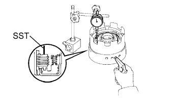
Using SST and a dial indicator, measure the direct clutch piston stroke while applying and releasing compressed air (392 kPa, 4.0 kgf/cm2, 57 psi).
- SST
- 09350-30020 ( 09350-06120 )
Pack Clearance 0.40 to 0.70 mm (0.016 to 0.028 in.) If the pack clearance is less than the limit of piston stroke, parts may have been assembled incorrectly, so check and reassemble again.
If the pack clearance is outside the standard, select another flange.
Tech Tips
There are 8 different flanges in thickness.
Flange thickness mm (in.) No. Thickness No. Thickness 53 3.3 (0.130) 57 3.7 (0.146) 54 3.4 (0.134) 58 3.8 (0.150) 55 3.5 (0.138) 60 4.0 (0.157) 56 3.6 (0.142) 62 4.2 (0.165)
-