AUTOMATIC TRANSMISSION UNIT (for 1KD-FTV) REASSEMBLY

-
BEARING POSITION
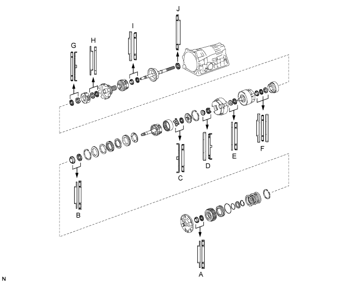
Standard Mark Front Race Diameter Inside / Outside mm (in.) Thrust Bearing Diameter Inside / Outside mm (in.) Rear Race Diameter Inside / Outside mm (in.) A 28.45 (1.120) / 47.4 (1.866) 29.0 (1.142) / 50.4 (1.984) - B 28.6 (1.126) / 46.7 (1.839) 28.8 (1.134) / 50.4 (1.984) - C 33.0 (1.299) / 50.4 (1.984) 31.4 (1.236) / 49.4 (1.945) - D 37.1 (1.461) / 59.0 (2.323) 33.6 (1.323) / 50.3 (1.980) - E 37.0 (1.457) / 51.0 (2.008) 33.5 (1.319) / 47.8 (1.882) - F 25.98 (1.023) / 48.87 (1.924) 25.9 (1.020) / 47.0 (1.854) 26.5 (1.043) / 47.02 (1.851) G - 35.0 (1.378) / 53.75 (2.116) 34.0 (1.339) / 48.0 (1.890) H 33.5 (1.319) / 47.8 (1.882) 35.4 (1.398) / 48.0 (1.890) - I 28.5 (1.122) / 44.2 (1.740) 27.5 (1.083) / 44.2 (1.740) - J - 40.5 (1.594) / 58.3 (2.295) - -
FIX AUTOMATIC TRANSMISSION CASE SUB-ASSEMBLY
-
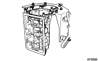
Install the automatic transmission case sub-assembly into the overhaul attachment.
-
-
INSTALL NO. 1 1ST AND REVERSE BRAKE PISTON
-
Coat 3 new O-rings with ATF.
-
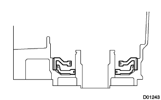
Install 2 O-rings onto the No. 1 1st and reverse brake piston.
-
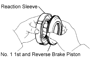
Install the remaining O-ring onto the brake reaction sleeve.
-
Install the No. 1 1st and reverse brake piston onto the brake reaction sleeve.
-
-
INSTALL BRAKE REACTION SLEEVE
-
With the No. 1 1st and reverse brake piston placed under the brake reaction sleeve, install the brake reaction sleeve and the No. 1 1st and reverse brake piston into the automatic transmission case sub-assembly.
Note
Be careful not to damage the O-rings.
-
-
INSTALL NO. 2 1ST AND REVERSE BRAKE PISTON
-
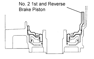
Coat a new O-ring with ATF, and install it onto the No. 2 1st and reverse brake piston.
-
Install the No. 2 1st and reverse brake piston onto the automatic transmission case sub-assembly.
Note
Be careful not to damage the O-ring.
-
-
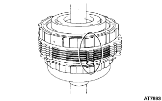
INSTALL 1ST AND REVERSE BRAKE RETURN SPRING SUB-ASSEMBLY
-
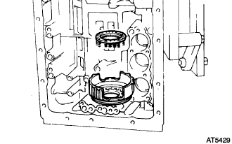
Place the 1st and reverse brake return spring sub-assembly onto the No. 2 1st and reverse brake piston.
-
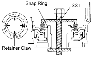
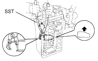
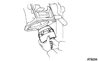
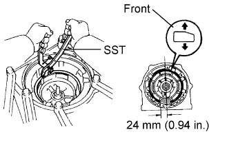
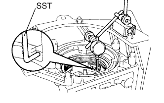
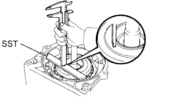
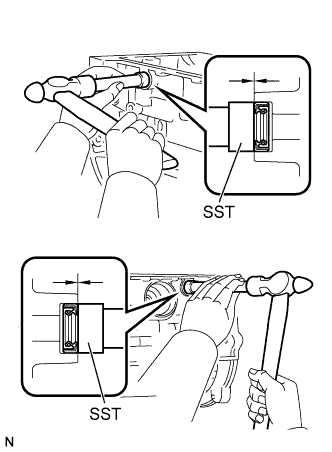
Set SST as shown, and compress the 1st and reverse brake return spring sub-assembly with SST.
- SST
- 09350-30020 ( 09350-07050, 09350-07070 )
Note
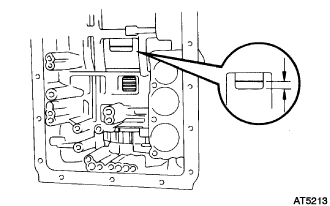
Stop compressing when the spring retainer is lowered to a position 1 to 2 mm (0.039 to 0.078 in.) from the snap ring groove, preventing the spring retainer from being deformed.
-
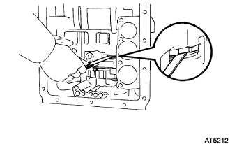
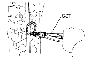
Using a screwdriver, install the snap ring. Make sure that the end gap of the snap ring is not aligned with the spring retainer claw.
-
-
INSPECT PISTON STROKE OF 1ST AND REVERSE BRAKE
-
Make sure that the No. 2 1st and reverse brake piston move smoothly when applying and releasing compressed air into the transmission case.
-
-
INSTALL REAR PLANETARY FLANGE THRUST NEEDLE ROLLER BEARING
-
Coat the thrust needle roller bearing with petroleum jelly, and instal it onto the automatic transmission case sub-assembly.
Bearing diameter Inside Outside 40.5 mm (1.594 in.) 58.3 mm (2.295 in.)
-
-
INSTALL REAR PLANETARY GEAR ASSEMBLY
-
Install the leaf spring.
-
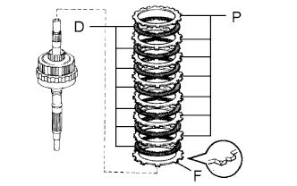
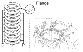
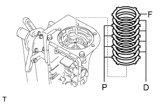
Install the 1st and reverse brake pack.
-
Install the flange with the rounded edge of the flange facing the disc.
-
Install the 7 discs and 7 plates.
Install in order D = Disc P = Plate D - P - D - P - D - P - D - P - D - P - D - P - D - P
-
-
Align the teeth on the flange, the discs and the plates.
-
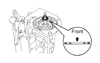
Face the snap ring upward (front side), and install the 2nd brake piston assembly onto the rear planetary gear assembly.
Note
Position the oil hole in the piston towards the lower side of the transmission case (the side where the valve body is installed).
-
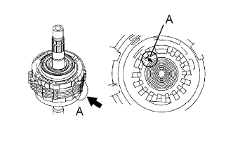
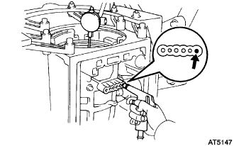
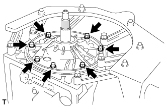
Align the splines, indicated by A, of the automatic transmission case sub-assembly, assembled 2nd brake piston assembly and 1st and reverse brake pack.
-
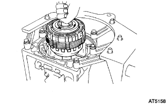
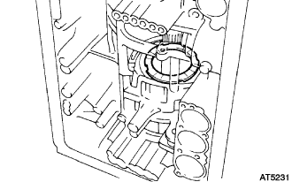
Install the assembled 2nd brake piston assembly, 1st and reverse brake pack, rear planetary gear assembly and the output shaft into the automatic transmission case sub-assembly.
-
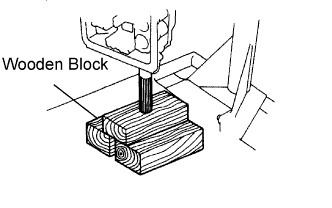
Place the output shaft on wooden blocks.
-
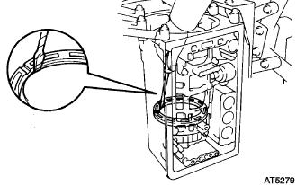
Using SST, install the snap ring.
- SST
- 09350-30020 ( 09350-07060 )
-
-
INSPECT PACK CLEARANCE OF 1ST AND REVERSE BRAKE
-
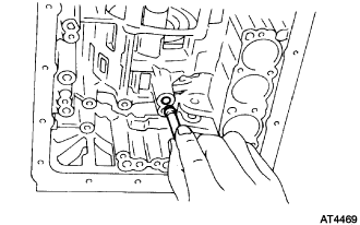
Using a feeler gauge, measure the clearance between the plate and the 2nd brake drum.
Standard clearance 0.70 to 1.22 mm (0.0276 to 0.0480 in.) If the clearance is outside the standard range, select another flange.
Flange thickness No. Thickness No. Thickness 67 5.4 mm (0.213 in.) 52 4.6 mm (0.181 in.) 66 5.2 mm (0.205 in.) 53 4.4 mm (0.173 in.) 50 5.0 mm (0.197 in.) 54 4.2 mm (0.165 in.) 51 4.8 mm (0.189 in.) 55 4.0 mm (0.157 in.)
-
-
INSTALL 2ND BRAKE PISTON SLEEVE
-
Using a screwdriver, install the 2nd brake piston sleeve.
Tech Tips
Tape up the screwdriver tip before use.
-
-
INSTALL BRAKE DRUM GASKET
-
Coat a new brake drum gasket with ATF, and install it into the automatic transmission case sub-assembly.
-
-
INSTALL 1 WAY CLUTCH ASSEMBLY
-
Install the No. 4 planetary carrier thrust washer onto the 2nd brake piston assembly.
-
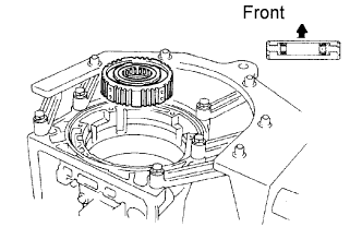
Install the 1 way clutch assembly.
-
-
INSTALL 2ND BRAKE PACK
-
Install a 1.8 mm (0.0709 in.) thick plate with its rounded edge facing the disc.
-
Install 2.5 mm (0.0984 in.) thick plates and discs.
Install in order D = Disc P = Plate D - P - D - P - D - P - D - P - D -
Install a 3.0 mm (0.1181 in.) thick flange with its rounded edge facing the disc.
-
Using a screwdriver, install the snap ring.
Tech Tips
Tape up the screwdriver tip before use.
-
-
INSPECT PACK CLEARANCE OF 2ND BRAKE
-
Using a feeler gauge, measure the clearance between the snap ring and the flange.
Standard clearance 0.62 to 1.98 mm (0.0244 to 0.0780 in.) If the clearance is outside the standard, check for improper installation.
-
-
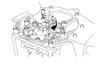
INSTALL PLANETARY SUN GEAR SUB-ASSEMBLY
-
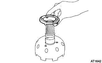
Coat the No. 2 planetary carrier thrust washer with petroleum jelly, and install it onto the planetary sun gear sub-assembly.
-
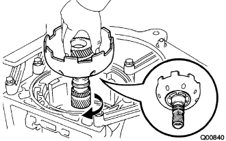
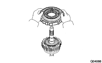
While turning the planetary sun gear sub-assembly clockwise, install it into the 1 way clutch assembly.
Tech Tips
Confirm the thrust washer is installed correctly.
-
-
INSTALL FRONT PLANETARY GEAR ASSEMBLY
-
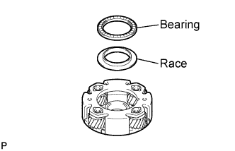
Coat the thrust needle roller bearing and the thrust bearing race with petroleum jelly, and install them onto the front planetary gear assembly.
Bearing and race diameter Inside Outside Bearing 35.4 mm (1.398 in.) 48.0 mm (1.890 in.) Race 33.5 mm (1.319 in.) 47.8 mm (1.882 in.) -
Install the front planetary gear assembly onto the planetary sun gear sub-assembly.
-
Using SST, install the snap ring.
- SST
- 09350-30020 ( 09350-07070 )
-
Remove the wooden blocks or equivalent out from under the output shaft.
-
Coat the thrust bearing race with petroleum jelly, and install it onto the front planetary gear assembly.
Race diameter Inside Outside 34.0 mm (1.339 in.) 48.0 mm (1.890 in.)
-
-
INSTALL 2ND COAST BRAKE BAND ASSEMBLY
-
Install the 2nd coast brake band assembly into the automatic transmission case sub-assembly.
-
Install the E-ring onto the pin.
-
Install the pin through the 2nd coast brake band assembly.
-
Install the E-ring onto the pin.
-
-
INSTALL FORWARD CLUTCH ASSEMBLY
-
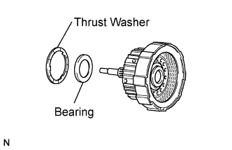
Install the thrust needle roller bearing and the No. 2 clutch drum thrust washer onto the forward clutch assembly.
Bearing diameter Inside Outside 33.5 mm (1.319 in.) 47.8 mm (1.882 in.) -
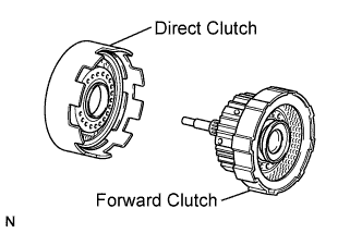
Install the forward clutch assembly onto the direct clutch assembly.
-
-
INSTALL FRONT PLANETARY RING GEAR SUB-ASSEMBLY
-
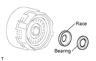
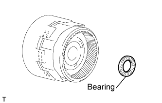
Coat the thrust needle roller bearing and the thrust bearing race with petroleum jelly, and install them onto the forward clutch assembly.
Bearing and race diameter Inside Outside Bearing 25.9 mm (1.020 in.) 47.0 mm (1.854 in.) Race 25.98 mm (1.023 in.) 48.87 mm (1.924 in.) -
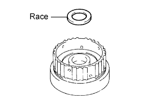
Coat the thrust bearing race with petroleum jelly, and install it onto the front planetary ring gear sub-assembly.
Race diameter Inside Outside 26.5 mm (1.043 in.) 47.02 mm (1.851 in.) -
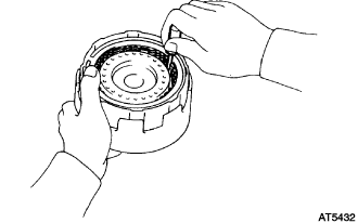
Align the flukes of the discs in the forward clutch assembly.
-
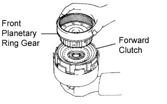
Align the splines of the front planetary ring gear sub-assembly with the flukes of the discs and install the front planetary ring gear sub-assembly into the forward clutch assembly.
-
-
INSTALL DIRECT CLUTCH ASSEMBLY
-
Coat the thrust needle roller bearing with petroleum jelly, and install it onto the front planetary ring gear sub-assembly.
Bearing diameter Inside Outside 35.0 mm (1.378 in.) 53.75 mm (2.116 in.) -
Install the assembled direct clutch assembly, forward clutch assembly and front planetary ring gear sub-assembly into the automatic transmission case sub-assembly.
-
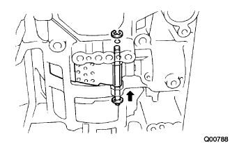
Using vernier calipers, measure the distance between the direct clutch assembly and the planetary sun gear assembly as shown in the illustration.
Standard distance 5.3 to 7.3 mm (0.2087 to 0.2874 in.) If the distance is outside the standard, check for improper installation.
-
-
INSTALL 2ND COAST BRAKE PISTON
-
Coat 2 new O-rings with ATF, and install them onto the 2nd coast brake cover.
-
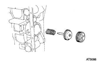
Install the spring, the 2nd coast brake piston and the 2nd coast brake cover into the automatic transmission case sub-assembly.
-
Using SST, install the snap ring.
- SST
- 09350-30020 ( 09350-07060 )
-
-
INSTALL OVERDRIVE SUPPORT SUB-ASSEMBLY
-
Coat the thrust needle roller bearing and the thrust bearing race with petroleum jelly, and install them onto the overdrive support sub-assembly.
Bearing and race diameter Inside Outside Race 37.0 mm (1.457 in.) 51.0 mm (2.008 in.) Bearing 33.6 mm (1.323 in.) 50.3 mm (1.980 in.) -
Coat the clutch drum thrust washer with petroleum jelly, and install it onto the overdrive support sub-assembly.
Tech Tips
Make sure that the lug shape fits into the hole on the overdrive support sub-assembly.
-
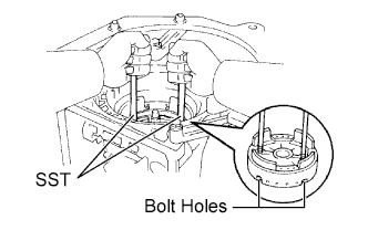
Using the 2 SST bolts, align the 2 bolt holes of the overdrive support sub-assembly with the bolt holes in the automatic transmission case sub-assembly and install the overdrive support sub-assembly into the automatic transmission case sub-assembly.
- SST
- 09350-30020 ( 09350-07020 )
-
Temporarily tighten the 2 bolts.
-
Using SST, install the snap ring.
- SST
- 09350-30020 ( 09350-07060 )
Tech Tips
Orient the snap ring open end toward the valve body.
-
Tighten the 2 bolts.
- Torque:
- 25 N*m { 260 kgf*cm, 19 ft.*lbf }
-
-
INSPECT OUTPUT SHAFT
-
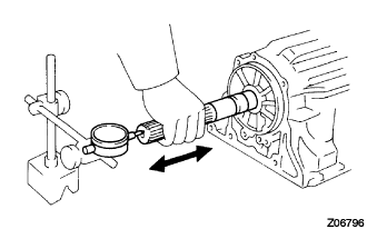
Using a dial indicator, measure the end play of the output shaft by hand.
End play 0.30 to 1.04 mm (0.0118 to 0.0409 in.) If the value is outside the standard range, check for improper installation.
-
Check that the output shaft rotates smoothly.
-
-
INSPECT PISTON STROKE OF 2ND COAST BRAKE
-
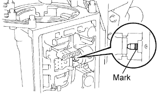
Place a mark on the 2nd coast brake piston rod.
-
Using SST, measure the stroke while applying and releasing compressed air (392 kPa, 4.0 kgf/cm2, 57 psi).
- SST
- 09240-00020
Piston rod stroke 1.50 to 3.00 mm (0.0591 to 0.1181 in.) If the stroke is outside the specified range, replace the piston rod.
Piston rod length 78.4 mm (3.087 in.) or 79.9 mm (3.146 in.) If the stroke is still outside the specified range, replace the 2nd coast brake band assembly with a new one.
-
-
INSTALL OVERDRIVE BRAKE PACK
-
Install the 4 plates and 4 discs.
Install in order P = Plate D = Disc P - D - P - D - P - D - P - D -
Install the flange (stepped ring) with the flat side of the flange facing the disc.
-
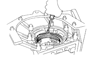
Using a screwdriver, install the snap ring.
Tech Tips
Tape up the screwdriver tip before use.
-
-
INSPECT OVERDRIVE BRAKE PISTON
-
Place SST and a dial indicator onto the overdrive brake piston.
- SST
- 09350-30020 ( 09350-06120 )
-
Measure the stroke while applying and releasing compressed air (392 kPa, 4.0 kgf/cm2, 57 psi).
Piston stroke 1.40 to 1.70 mm (0.0551 to 0.0669 in.) If the piston stroke is less than the limit, parts may be assembled incorrectly, so check and reassemble them if necessary.
If the piston stroke is still outside the specified range, select another flange.
Tech Tips
There are 7 different thicknesses for the flange.
Flange thickness No. Thickness No. Thickness 77 3.3 mm (0.130 in.) 81 3.8 mm (0.150 in.) 78 3.5 mm (0.138 in.) 82 3.9 mm (0.154 in.) 79 3.6 mm (0.142 in.) 83 4.0 mm (0.157 in.) 80 3.7 mm (0.146 in.) - -
-
-
INSTALL OVERDRIVE PLANETARY RING GEAR
-
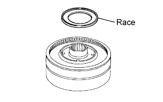
Coat the thrust bearing race with petroleum jelly, and install it onto the overdrive planetary ring gear.
Race diameter Inside Outside 37.1 mm (1.461 in.) 59.0 mm (2.323 in.) -
Install the overdrive planetary ring gear.
-
Coat the thrust needle roller bearing with petroleum jelly, and install it onto the overdrive planetary ring gear.
Bearing diameter Inside Outside 31.4 mm (1.236 in.) 49.4 mm (1.945 in.)
-
-
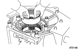
INSTALL OVERDRIVE PLANETARY GEAR ASSEMBLY
-
Coat the thrust bearing race with petroleum jelly, and install it onto the overdrive planetary gear assembly.
Race diameter Inside Outside 33.0 mm (1.299 in.) 50.4 mm (1.984 in.) -
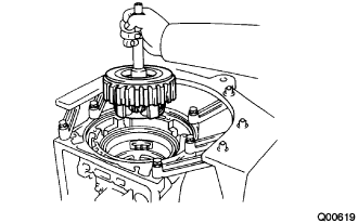
Install the overdrive planetary gear assembly.
-
Place SST on the automatic transmission case sub-assembly.
- SST
- 09350-36010 ( 09350-06090 )
-
Using vernier calipers, measure the distance between the tops of SST and the overdrive direct clutch drum sub-assembly.
Standard distance 15.5 to 16.5 mm (0.610 to 0.650 in.) If the distance is outside the standard range, check for improper installation.
-
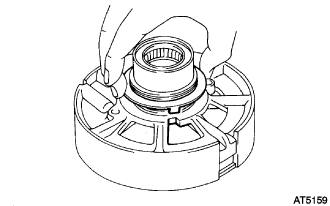
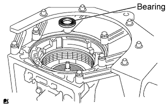
Coat the thrust needle roller bearing with petroleum jelly, and install it onto the overdrive direct clutch drum sub-assembly.
Bearing diameter Inside Outside 29.0 mm (1.142 in.) 50.4 mm (1.984 in.)
-
-
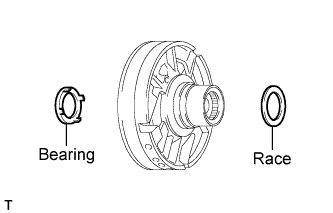
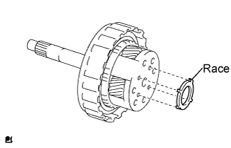
INSTALL FRONT OIL PUMP BODY SUB-ASSEMBLY
-
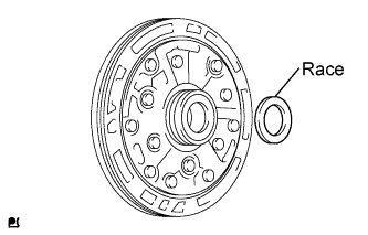
Coat the thrust bearing race with petroleum jelly, and install it onto the front oil pump body sub-assembly.
Race diameter Inside Outside 28.45 mm (1.120 in.) 47.4 mm (1.866 in.) -
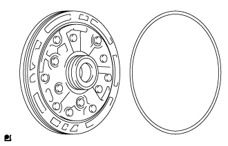
Coat a new O-ring with ATF, and install it around the front oil pump body sub-assembly.
-
Coat the 2 oil seal rings with ATF.
-
Place the front oil pump body sub-assembly through the input shaft, and align the bolt holes of the front oil pump body sub-assembly and the automatic transmission case sub-assembly.
-
Hold the input shaft, and lightly press the oil pump body to slide the oil seal rings into the overdrive direct clutch drum sub-assembly.
Note
Do not push on the oil pump strongly, or the oil seal ring will stick to the direct clutch drum.
-
Install the 7 bolts.
- Torque:
- 21 N*m { 214 kgf*cm, 16 ft.*lbf }
-
-
INSPECT INPUT SHAFT SUB-ASSEMBLY
-
Make sure that the input shaft rotates smoothly.
-
-
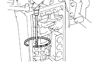
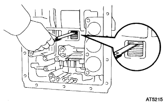
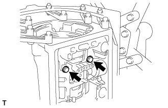
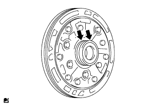
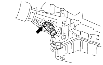
INSPECT INDIVIDUAL PISTON OPERATION INSPECTION
-
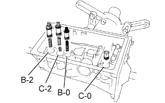
Check for the sound while applying compressed air into the oil hole indicated in the illustration.
Tech Tips
Inspect the overdrive direct clutch with the C-0 accumulator piston hole closed. If there is no sounds from the overdrive direct clutch, disassemble and check the installation conditions of the following parts:
-
Overdrive direct clutch
-
Direct clutch
-
Forward clutch
-
Overdrive brake
-
2nd coast brake
-
2nd brake
-
1st and reverse brake
-
-
-
INSTALL MANUAL VALVE LEVER SHAFT OIL SEAL
-
Using SST and a hammer, drive in 2 new manual valve lever shaft oil seals.
- SST
- 09350-30020 ( 09350-07110 )
Drive in depth 0 to 0.3 mm (0 to 0.012 in.) -
Coat the oil seal lip with MP grease.
-
-
INSTALL MANUAL VALVE LEVER SUB-ASSEMBLY
-
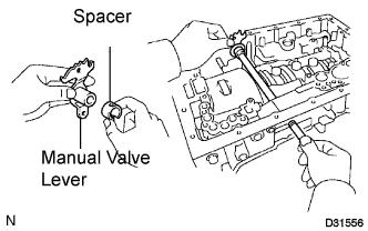
Install a new spacer onto the manual valve lever sub-assembly.
-
Install the manual valve lever shaft into the automatic transmission case sub-assembly through the manual valve lever sub-assembly.
-
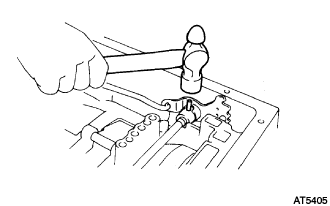
Using a hammer, drive in a new pin.
-
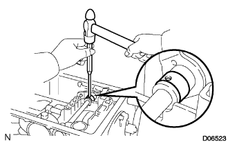
Align the indentation on the manual valve lever sub-assembly with the spacer hole, and stake them with a punch.
-
Make sure that the shaft rotates smoothly.
-
-
INSTALL PARKING LOCK PAWL SHAFT
-
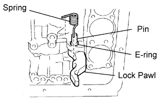
Install the E-ring onto the parking lock pawl shaft.
-
Install the parking lock pawl, the packing lock pawl shaft and the spring.
-
-
INSTALL PARKING LOCK ROD SUB-ASSEMBLY
-
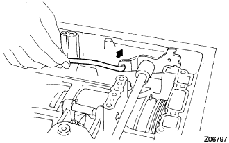
Connect the parking lock rod sub-assembly to the manual valve lever sub-assembly.
-
-
INSTALL PARKING LOCK PAWL BRACKET
-
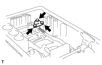
Install the parking lock pawl bracket with the 3 bolts.
- Torque:
- 7.4 N*m { 75 kgf*cm, 65 in.*lbf }
-
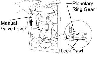
Shift the manual valve lever to the P position, and confirm that the planetary ring gear is correctly locked up by the lock pawl.
-
-
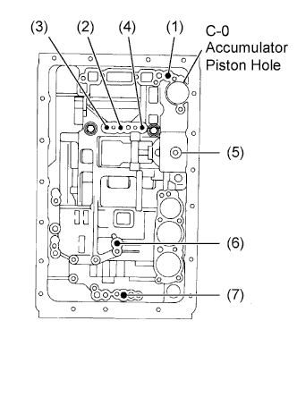
INSTALL C-0 ACCUMULATOR PISTON
-
Coat a new O-ring with ATF, and install it onto the C-0 accumulator piston.
-
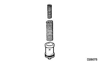
Install the 2 springs and C-0 accumulator piston into the hole.
Accumulator spring Spring Outer diameter
mm (in.)
Free length
mm (in.)
Color C-0 Inner 14.02 (0.552) 46.0 (1.811) Yellow C-0 Outer 20.9 (0.823) 74.6 (2.137) Orange
-
-
INSTALL B-0 ACCUMULATOR PISTON
-
Coat 2 new O-rings with ATF, and install them onto the B-0 accumulator piston.
-
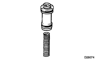
Install the spring and the B-0 accumulator piston into the hole.
Accumulator spring Spring Outer diameter
mm (in.)
Free length
mm (in.)
Color B-0 16.0 (0.630) 63.6 (2.504) Red
-
-
INSTALL C-2 ACCUMULATOR PISTON
-
Coat 2 new O-rings with ATF, and install them onto the C-2 accumulator piston.
-
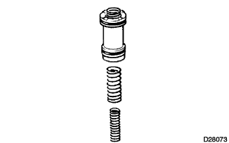
Install the 2 springs and the C-2 accumulator piston into the hole.
Accumulator spring Spring Outer diameter
mm (in.)
Free length
mm (in.)
Color C-2 Inner 14.7 (0.579) 42.1 (1.657) Pink C-2 Outer 20.2 (0.795) 68.6 (2.701) Blue
-
-
INSTALL B-2 ACCUMULATOR PISTON
-
Coat 2 new O-rings with ATF, and install them onto the B-2 accumulator piston.
-
Install the spring and the B-2 accumulator piston into the hole.
Accumulator spring Spring Outer diameter
mm (in.)
Free length
mm (in.)
Color B-2 19.9 (0.784) 73.4 (2.890) Red
-
-
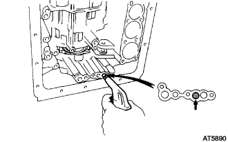
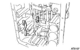
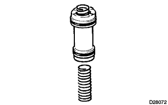
INSTALL CHECK BALL BODY
-
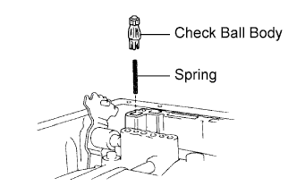
Install the check ball body and spring.
-
-
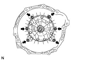
INSTALL TRANSMISSION VALVE BODY ASSEMBLY
-
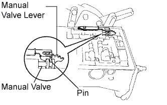
Align the groove of the manual valve with the pin of the manual valve lever.
-
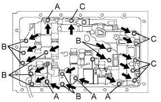
Install the 20 bolts.
- Torque:
- 11 N*m { 112 kgf*cm, 8 ft.*lbf }
Bolt length 23 mm (0.91 in.) for bolt A 28 mm (1.10 in.) for bolt B 36 mm (1.42 in.) for bolt C
-
-
INSTALL TRANSMISSION WIRE
-
Coat a new O-ring with ATF, and install it onto the transmission wire.
-
Install the transmission wire into the automatic transmission case sub-assembly with the bolt.
- Torque:
- 5.4 N*m { 55 kgf*cm, 48 in.*lbf }
-
w/o Flex Lock-up:
Connect the 4 connectors.
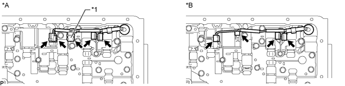
Text in Illustration *A w/ Flex Lock-up *B w/o Flex Lock-up *1 ATF Temperature Sensor - - -
w/ Flex Lock-up:
-
Attach the ATF temperature sensor to the temperature sensor clamp.
-
Connect the 4 connectors.
-
-
-
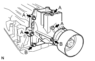
INSTALL VALVE BODY OIL STRAINER ASSEMBLY
-
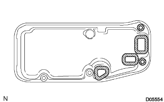
Install 5 new gaskets onto the valve body oil strainer assembly.
-
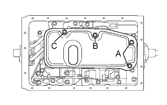
Install the valve body oil strainer assembly with the 4 bolts.
- Torque:
- 11 N*m { 112 kgf*cm, 8 ft.*lbf }
Bolt length 14 mm (0.55 in.) for bolt A 20 mm (0.79 in.) for bolt B 23 mm (0.91 in.) for bolt C
-
-
INSTALL AUTOMATIC TRANSMISSION OIL PAN SUB-ASSEMBLY
-
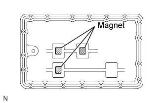
Install the 3 oil cleaner magnets onto the automatic transmission oil pan sub-assembly.
-
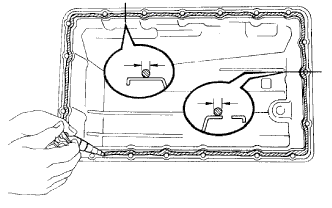
Remove any FIPG material while being careful not to drop oil on the contacting surfaces of the transmission case and the automatic transmission oil pan sub-assembly.
-
Apply FIPG to the automatic transmission oil pan sub-assembly.
FIPG Toyota Genuine Seal Packing 1281, Three Bond 1281 or equivalent Note
Apply a continuous line of FIPG (width 2.0 to 3.0 mm (0.08 to 0.12 in.)) to the sealing surface.
-
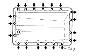
Install the automatic transmission oil pan sub-assembly with the 19 bolts.
- Torque:
- 7.4 N*m { 75 kgf*cm, 65 in.*lbf }
Note
Install the bolts and tighten them within 10 minutes of applying the FIPG.
-
-
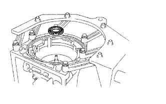
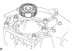
INSTALL SENSOR ROTOR (w/o Speedometer Sensor)
-
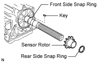
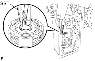
Using a snap ring expander, install the front side snap ring.
-
Install the key and sensor rotor.
-
Using a snap ring expander, install the rear side snap ring.
-
-
INSTALL SENSOR ROTOR (w/ Speedometer Sensor)
-
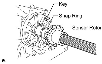
Using a snap ring expander, install the snap ring.
-
Install the key and sensor rotor.
-
-
INSTALL SPEEDOMETER DRIVE GEAR (w/ Speedometer Sensor)
-
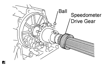
Install the ball and the speedometer drive gear.
-
Using a snap ring expander, install the snap ring.
-
-
INSTALL EXTENSION HOUSING DUST DEFLECTOR
-
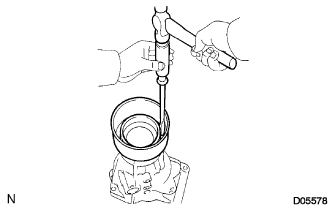
Using a screwdriver and hammer, install a new extension housing dust deflector.
-
-
INSTALL AUTOMATIC TRANSMISSION EXTENSION HOUSING OIL SEAL
-
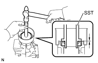
Using SST and a hammer, install a new automatic transmission extension housing oil seal.
- SST
- 09950-60020 ( 09951-00580 )
- 09950-70010 ( 09951-07100 )
Drive in depth 6.0 +/- 0.2 mm (0.236 +/- 0.008 in.) -
Coat the oil seal lip with MP grease.
-
-
INSTALL EXTENSION HOUSING BUSH APPLY TUBE
-
Install a new extension housing bush apply tube.
-
-
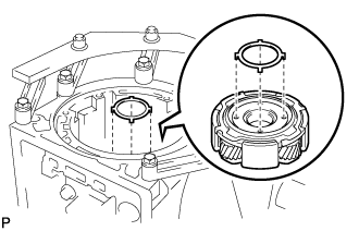
INSTALL EXTENSION HOUSING BUSH APPLY TUBE GASKET
-
Install a new extension housing bush apply tube gasket.
-
-
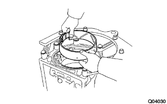
INSTALL EXTENSION HOUSING SUB-ASSEMBLY
-
Apply adhesive to the 6 bolts.
Adhesive Toyota Genuine Adhesive 1344, Three Bond 1344 or equivalent -
Install the extension housing sub-assembly and a new extension housing gasket into the automatic transmission case sub-assembly with the 6 bolts.
- Torque:
- 34 N*m { 347 kgf*cm, 25 ft.*lbf }
Bolt length 45 mm (1.772 in.) for Bolt A 35 mm (1.378 in.) for Bolt B
-
-
INSTALL AUTOMATIC TRANSMISSION HOUSING
-
Clean the threads of the bolts and the automatic transmission case sub-assembly with non-residue solvent.
-
Apply adhesive to the 6 bolts.
Adhesive Toyota Genuine Adhesive 1344, Three Bond 1344 or equivalent -
Install the automatic transmission housing with the 6 bolts.
- Torque:
- 14 mm bolt
- 34 N*m { 347 kgf*cm, 25 ft.*lbf }
- 17 mm bolt
- 57 N*m { 580 kgf*cm, 42 ft.*lbf }
-
-
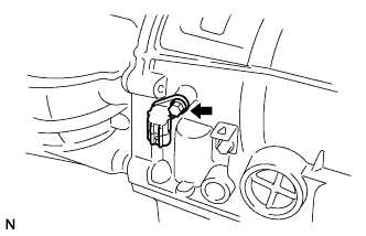
INSTALL SPEED SENSOR SP2
-
Coat a new O-ring with ATF, and install it onto the speed sensor SP2.
-
Install the speed sensor SP2 with the bolt.
- Torque:
- 5.4 N*m { 55 kgf*cm, 48 in.*lbf }
-
-
INSTALL SPEED SENSOR NC0
-
Coat a new O-ring with ATF, and install it onto the speed sensor NC0.
-
Install the speed sensor NC0 with the bolt.
- Torque:
- 5.4 N*m { 55 kgf*cm, 48 in.*lbf }
-
-
INSTALL SPEEDOMETER SENSOR (w/ Speedometer Sensor)
-
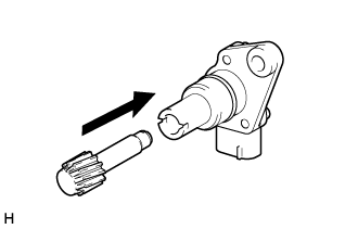
Install the speedometer driven gear to the speedometer sensor.
Tech Tips
Insert the speedometer driven gear so that the gear's grooves align with the protrusions inside the speedometer sensor.
-
Coat a new O-ring with ATF, and install it onto the speedometer sensor.
-
Install the speedometer sensor with the bolt.
- Torque:
- 5.4 N*m { 55 kgf*cm, 48 in.*lbf }
-
-
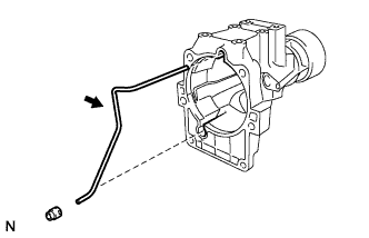
INSTALL BREATHER HOSE
-
Install the breather hose with the bolt.
- Torque:
- 7.4 N*m { 75 kgf*cm, 65 in.*lbf }
-
-
INSTALL OIL COOLER TUBE UNION
-
Coat 2 new O-rings with ATF, and install them onto each oil cooler tube union.
-
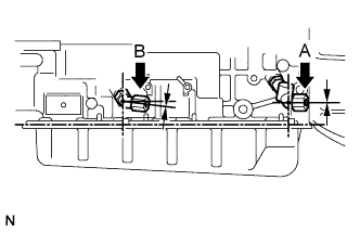
Install the 2 oil cooler tube unions.
- Torque:
- 29 N*m { 300 kgf*cm, 22 ft.*lbf }
Union installation angle 0° +/- 2° for Union A 7° +/- 2° for Union B
-
-
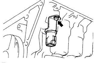
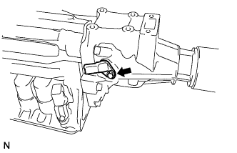
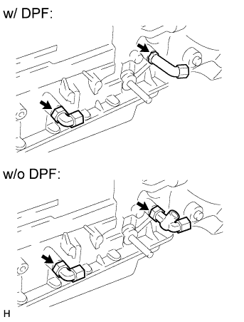
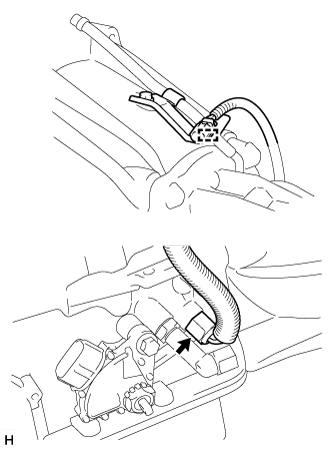
INSTALL TEMPERATURE SENSOR (w/ DPF)
-
Coat a new O-ring with ATF and install it to the temperature sensor.
-
Using a 19 mm union nut wrench, Install the temperature sensor.
- Torque:
- 29 N*m { 300 kgf*cm, 22 ft.*lbf }
Note
Use the formula to calculate special torque value for situations where a union nut wrench is combined with a torque wrench Click here.
-
Connect the temperature sensor connector clamp to the wire harness bracket.
-
-
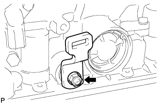
INSTALL TEMPERATURE SENSOR (w/o DPF)
-
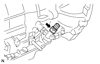
Coat a new O-ring with ATF, and install it onto the temperature sensor.
-
Install the temperature sensor.
- Torque:
- 15 N*m { 152 kgf*cm, 11 ft.*lbf }
-
-
INSTALL PARK/NEUTRAL POSITION SWITCH ASSEMBLY
-
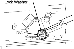
Install the park/neutral position switch assembly onto the manual valve lever shaft, and temporarily tighten the adjusting bolt.
-
Install a new lock washer, and then install the nut.
- Torque:
- 6.9 N*m { 70 kgf*cm, 61 in.*lbf }
-
Using the control shaft lever, fully turn the manual lever shaft back, and then return 2 notches. Make sure that it is now in the N position.
-
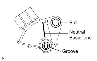
Align the neutral basic line with the switch groove, and tighten the bolt.
- Torque:
- 13 N*m { 130 kgf*cm, 9 ft.*lbf }
-
Bend the tabs of the lock washer.
Tech Tips
Bend at least 2 of the lock washer tabs.
-
-
INSTALL TRANSMISSION CONTROL SHAFT LEVER LH
-
Install the transmission control shaft lever LH with the washer and the nut.
- Torque:
- 16 N*m { 160 kgf*cm, 12 ft.*lbf }
-
-
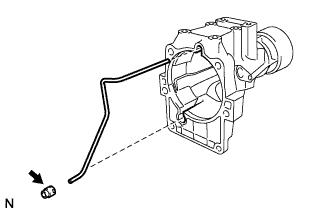
INSTALL BREATHER PLUG HOSE
-
Install the breather plug hose with the bolt.
- Torque:
- 7.4 N*m { 75 kgf*cm, 65 in.*lbf }
-