AUTOMATIC TRANSMISSION UNIT INSPECTION

-
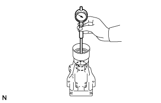
INSPECT EXTENSION HOUSING SUB-ASSEMBLY
-
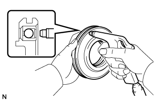
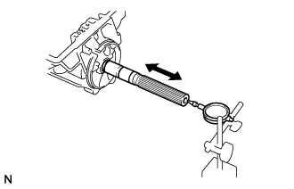
Using a cylinder gauge, measure the inside diameter of the extension housing sub-assembly bush.
Maximum inside diameter 38.09 mm (1.50 in.) If the inside diameter is more than the maximum, replace the extension housing sub-assembly.
-
-
INSPECT AUTOMATIC TRANSMISSION OIL PAN SUB-ASSEMBLY
-
Remove the 2 automatic transmission oil cleaner magnets and use them to collect steel particles. Carefully look at the foreign matter and particles in the automatic transmission oil pan sub-assembly and on the 2 automatic transmission oil cleaner magnets to determine the type of wear you will find in the automatic transmission assembly.
Steel (magnetic): bearing, gear and clutch plate wear
Brass (non-magnetic): bush wear
-
-
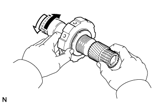
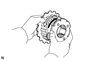
INSPECT OVERDRIVE ONE-WAY CLUTCH
-
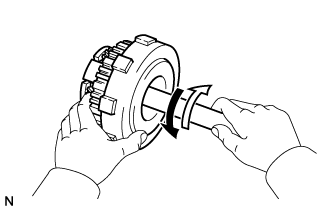
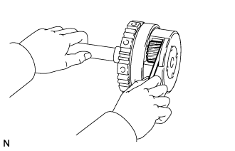
Hold the overdrive direct clutch drum sub-assembly and turn the overdrive planetary gear assembly. Check that the overdrive planetary gear assembly can be turned clockwise but cannot be turned counterclockwise.
Text in Illustration 
Lock 
Free
-
-
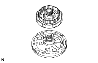
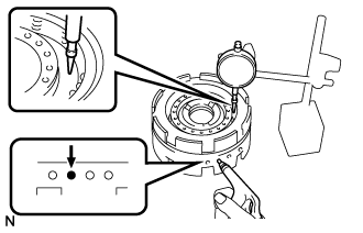
INSPECT PISTON STROKE OF OVERDRIVE DIRECT CLUTCH PISTON SUB-ASSEMBLY
-
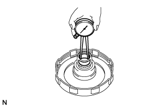
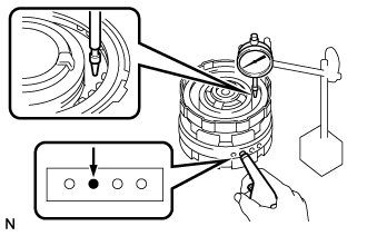
Place the overdrive direct clutch drum sub-assembly onto the oil pump assembly.
-
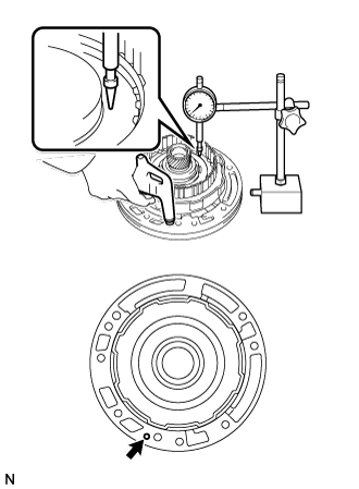
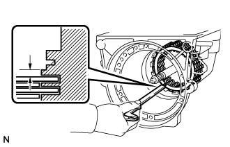
Using a dial indicator, measure the overdrive direct clutch piston sub-assembly stroke by applying and releasing compressed air (392 kPa (4.0 kgf/cm2, 57 psi)) as shown in the illustration.
Standard piston stroke 1.74 to 2.44 mm (0.0686 to 0.0960 in.) If the result is not as specified, inspect the overdrive clutch disc set.
-
Remove the overdrive direct clutch drum sub-assembly from the oil pump assembly.
-
-
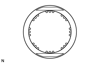
INSPECT OVERDRIVE CLUTCH DISC
-

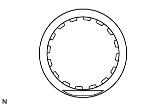
Check whether the sliding surfaces of the overdrive clutch disc and overdrive clutch flange are worn or burnt.
If necessary, replace the disc and flange.
Note
-
If the lining of the overdrive clutch disc is peeled off or discolored, or if any part of the printed numbers are damaged, replace the disc.
-
Before assembling a new disc, soak it in ATF for at least 15 minutes.
-
-
-
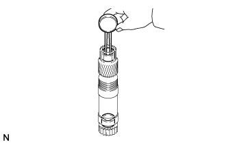
INSPECT OVERDRIVE DIRECT CLUTCH PISTON SUB-ASSEMBLY
-
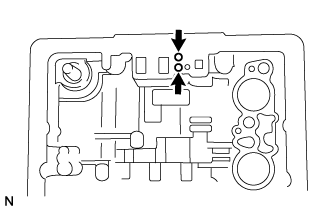
Check that the check ball is free by shaking the overdrive direct clutch piston.
-
Check that the valve does not have leaks by applying low-pressure compressed air.
-
-
INSPECT OVERDRIVE DIRECT CLUTCH DRUM SUB-ASSEMBLY
-
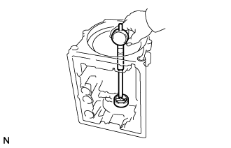
Using a caliper gauge, measure the inside diameter of the overdrive direct clutch drum sub-assembly bush.
Maximum inside diameter 23.14 mm (0.911 in.) If the inside diameter is more than the maximum, replace the overdrive direct clutch drum sub-assembly.
-
-
INSPECT OVERDRIVE PLANETARY GEAR ASSEMBLY
-
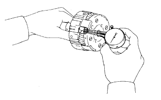
Using a caliper gauge, measure the inside diameter of the overdrive planetary gear assembly bush.
Maximum inside diameter 11.27 mm (0.444 in.) If the inside diameter is more than the maximum, replace the overdrive planetary gear assembly.
-
Using a feeler gauge, measure the planetary pinion gear thrust clearance.
Standard clearance 0.20 to 0.50 mm (0.00788 to 0.0196 in.) If the clearance is not as specified, inspect the planetary gear thrust washer. If necessary, replace the overdrive planetary gear assembly.
-
-
INSPECT PISTON STROKE OF OVERDRIVE BRAKE PISTON
-
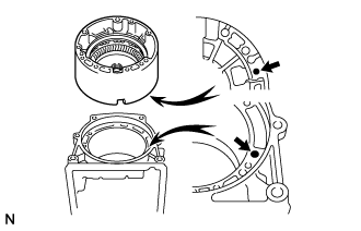
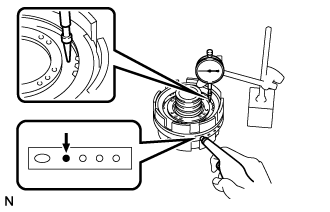
Place the overdrive case sub-assembly onto the transmission case with the cutout of the overdrive case sub-assembly facing downward.
Tech Tips
Make sure that the oil hole of the overdrive case sub-assembly is aligned with the oil hole of the transmission case.
-
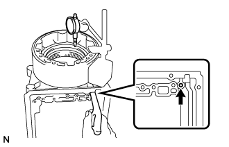
Using a dial indicator, measure the overdrive brake disc set pack clearance by applying and releasing compressed air (392 kPa (4.0 kgf/cm2, 57 psi)) as shown in the illustration.
Standard pack clearance 0.75 to 1.25 mm (0.0296 to 0.0492 in.) If the piston stroke is not as specified, parts may have been assembled incorrectly. Check the parts and reassemble again.
Tech Tips
-
If the piston stroke is still not as specified, replace the plates with ones of a different thickness.
-
There are 2 types of plates that can be used to adjust the pack clearance. Select the one with the most appropriate thickness.
Plate Thickness Part No. Thickness 35634-30080 1.95 to 2.05 mm (0.0768 to 0.0807 in.) 34634-30010 2.25 to 2.35 mm (0.0886 to 0.0925 in.) -
-
Remove the overdrive case sub-assembly from the transmission case.
-
-
INSPECT OVERDRIVE BRAKE DISC
-
Check whether the sliding surfaces of the overdrive brake discs, plates and flange are worn or burnt.
If necessary, replace the overdrive brake discs, plates and flange.
Note
-
If the lining of an overdrive brake disc is peeled off or discolored, or if any part of the printed numbers are damaged, replace all the overdrive brake discs.
-
Before assembling new overdrive brake discs, soak them in ATF for at least 15 minutes.
-
-
-
INSPECT PISTON STROKE OF FRONT CLUTCH PISTON SUB-ASSEMBLY
-
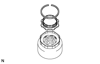
In order to check the piston stroke, install the rear clutch hub.
-
Install the snap ring.
-
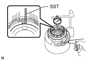
Using SST and a dial indicator, measure the front clutch piston sub-assembly stroke by applying and releasing compressed air (392 kPa (4.0 kgf/cm2, 57 psi)) as shown in the illustration.
- SST
- 09350-20015 ( 09350-06120 )
Standard piston stroke 1.40 to 1.60 mm (0.0552 to 0.0629 in.) If the piston stroke is not as specified, parts may have been assembled incorrectly. Check the parts and reassemble again.
Tech Tips
-
If the piston stroke is still not as specified, replace the plates with ones of a different thickness.
-
There are 2 types of plates that can be used to adjust the pack clearance. Select the one with the most appropriate thickness.
Plate Thickness Part No. Thickness 35634-22040 1.75 to 1.85 mm (0.0689 to 0.0728 in.) 34634-30070 1.95 to 2.05 mm (0.0768 to 0.0807 in.)
-
-
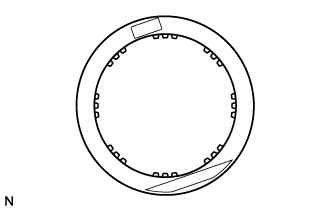
INSPECT FRONT CLUTCH DISC
-
Check whether the sliding surfaces of the front clutch discs and plates are worn or burnt.
If necessary, replace them.
Note
-
If the lining of a disc is peeled off or discolored, or if any part of the printed numbers are damaged, replace all the front clutch discs.
-
Before assembling new front clutch discs, soak them in ATF for at least 15 minutes.
-
-
-
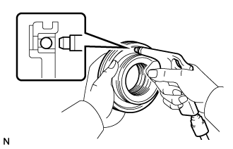
INSPECT FRONT CLUTCH PISTON SUB-ASSEMBLY
-
Check that the check ball is free by shaking the front clutch piston sub-assembly.
-
Check that the valve does not have leaks by applying low-pressure compressed air.
-
-
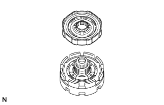
INSPECT PISTON STROKE OF REAR CLUTCH PISTON SUB-ASSEMBLY
-
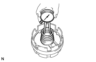
Place the rear clutch drum onto the center support sub-assembly.
-
Using a dial indicator, measure the rear clutch piston stroke by applying and releasing compressed air (392 kPa (4.0 kgf/cm2, 57 psi)) as shown in the illustration.
Standard piston stroke 0.90 to 1.30 mm (0.0355 to 0.0511 in.) If the piston stroke is not as specified, parts may have been assembled incorrectly. Check the parts and reassemble again.
Tech Tips
-
If the piston stroke is still not as specified, replace the flange with one of a different thickness.
-
There are 3 types of flanges that can be used to adjust the pack clearance. Select the one with the most appropriate thickness.
Flange Thickness Part No. Mark Thickness 35675-22120 A 3.475 to 3.600 mm (0.137 to 0.141 in.) 35675-22130 B 3.675 to 3.800 mm (0.145 to 0.149 in.) 35675-22140 - 3.925 to 4.050 mm (0.155 to 0.159 in.)
-
-
-
INSPECT REAR CLUTCH DISC
-
Check whether the sliding surfaces of the rear clutch discs, plates and rear clutch flange are worn or burnt.
If necessary, replace them.
Note
-
If the lining of a rear clutch disc is peeled off or discolored, or if any part of the printed numbers are damaged, replace all the rear clutch discs.
-
Before assembling new rear clutch discs, soak them in ATF for at least 15 minutes.
-
-
-
INSPECT REAR CLUTCH PISTON SUB-ASSEMBLY
-
Check that the check ball is free by shaking the rear clutch piston sub-assembly.
-
Check that the valve does not have leaks by applying low-pressure compressed air.
-
-
INSPECT PISTON STROKE OF NO. 1 BRAKE PISTON
-
Using a dial indicator, measure the No. 1 brake piston stroke by applying and releasing compressed air (392 kPa (4.0 kgf/cm2, 57 psi)) as shown in the illustration.
Standard piston stroke 0.75 to 1.35 mm (0.0296 to 0.0531 in.) If the stroke is not as specified, inspect the No. 1 brake discs.
-
-
INSPECT NO. 1 BRAKE DISC
-
Check whether the sliding surfaces of the No. 1 brake discs, plates and flange are worn or burnt.
If necessary, replace them.
Note
-
If the lining of a No. 1 brake disc is peeled off or discolored, or if any part of the printed numbers are damaged, replace all the No. 1 brake discs.
-
Before assembling new No. 1 brake discs, soak them in ATF for at least 15 minutes.
-
-
-
INSPECT CENTER SUPPORT SUB-ASSEMBLY
-
Using a caliper gauge, measure the inside diameter of the center support sub-assembly bush.
Maximum inside diameter 36.41 mm (1.43 in.) If the inside diameter is more than the maximum, replace the center support sub-assembly.
-
-
INSPECT PISTON STROKE OF NO. 2 BRAKE PISTON
-
Using a dial indicator, measure the No. 2 brake piston stroke by applying and releasing compressed air (392 kPa (4.0 kgf/cm2, 57 psi)) as shown in the illustration.
Standard piston stroke 0.98 to 1.71 mm (0.0386 to 0.0673 in.) If the stroke is not as specified, inspect the No. 2 brake discs.
-
-
INSPECT NO. 2 BRAKE DISC
-
Check whether the sliding surfaces of the No. 2 brake discs, plates and No. 2 brake flange are worn or burnt.
If necessary, replace them.
Note
-
If the lining of a No. 2 brake disc is peeled off or discolored, or if any part of the printed numbers are damaged, replace all the No. 2 brake discs.
-
Before assembling new No. 2 brake discs, soak them in ATF for at least 15 minutes.
-
-
-
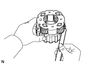
INSPECT NO. 1 ONE-WAY CLUTCH
-
Hold the No. 1 one-way clutch and turn the planetary sun gear sub-assembly. Check that the planetary sun gear sub-assembly can be turned counterclockwise but cannot be turned clockwise.
Text in Illustration Lock Free
-
-
INSPECT PLANETARY SUN GEAR SUB-ASSEMBLY
-
Using a caliper gauge, measure the inside diameter of the planetary sun gear sub-assembly bush.
Maximum inside diameter 21.53 mm (0.848 in.) If the inside diameter is more than the maximum, replace the planetary sun gear sub-assembly.
-
-
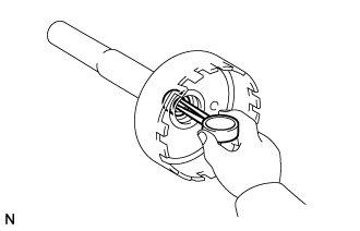
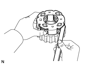
INSPECT NO. 2 ONE-WAY CLUTCH
-
Hold the No. 2 one-way clutch inner race sub-assembly and turn the front planetary gear sub-assembly. Check that the front planetary gear sub-assembly can be turned counterclockwise but cannot be turned clockwise.
Text in Illustration Lock Free
-
-
INSPECT FRONT PLANETARY GEAR SUB-ASSEMBLY
-
Using a feeler gauge, measure the planetary pinion gear thrust clearance.
Standard clearance 0.20 to 0.50 mm (0.00788 to 0.0196 in.) If the clearance is not as specified, inspect the planetary gear thrust washer. If necessary, replace the front planetary gear sub-assembly.
-
-
INSPECT OUTPUT SHAFT ASSEMBLY
-
Using a caliper gauge, measure the inside diameter of the output shaft assembly bush.
Maximum inside diameter 18.03 mm (0.710 in.) If the inside diameter is more than the maximum, replace the output shaft assembly.
-
-
INSPECT REAR PLANETARY GEAR ASSEMBLY
-
Using a feeler gauge, measure the planetary pinion gear thrust clearance.
Standard clearance 0.20 to 0.50 mm (0.00788 to 0.0196 in.) If the clearance is not as specified, inspect the planetary gear thrust washer. If necessary, replace the rear planetary gear assembly.
-
-
INSPECT PACK CLEARANCE OF NO. 3 BRAKE DISC SET
-
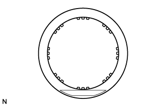
Using a vernier caliper, measure the clearance between the No. 3 brake disc and transmission case as shown in the illustration.
Standard pack clearance 0.52 to 1.27 mm (0.0205 to 0.0499 in.) Tech Tips
-
If the result is not as specified, replace the pressure plate with one of a different thickness.
-
There are 6 types of pressure plates that can be used to adjust the pack clearance. Select the one with the most appropriate thickness.
Pressure Plate Thickness Part No. Mark Thickness 35639-22010 - 2.95 to 3.05 mm (0.117 to 0.120 in.) 35639-22020 325 3.20 to 3.30 mm (0.126 to 0.129 in.) 35639-22030 350 3.45 to 3.55 mm (0.136 to 0.139 in.) 35639-22040 375 3.70 to 3.80 mm (0.146 to 0.149 in.) 35639-22050 400 3.95 to 4.05 mm (0.156 to 0.159 in.) 35639-22060 425 4.20 to 4.30 mm (0.166 to 0.169 in.) -
-
-
INSPECT NO. 3 BRAKE DISC
-
Check whether the sliding surfaces of the No. 3 brake discs and plates are worn or burnt.
If necessary, replace them.
Note
-
If the lining of a No. 3 brake disc is peeled off or discolored, or if any part of the printed numbers are damaged, replace all the No. 3 brake discs.
-
Before assembling new No. 3 brake discs, soak them in ATF for at least 15 minutes.
-
-
-
INSPECT NO. 3 BRAKE PISTON MOVEMENT
-
Check that the No. 3 brake pistons move smoothly when applying compressed air into and releasing compressed air from the transmission case.
-
-
INSPECT TRANSMISSION CASE
-
Using a cylinder gauge, measure the inside diameter of the transmission case bush.
Maximum inside diameter 38.19 mm (1.50 in.) If the inside diameter is more than the maximum, replace the transmission case.
-
-
INSPECT OUTPUT SHAFT ASSEMBLY
-
Using a dial indicator, measure the end play of the output shaft assembly while moving the output shaft assembly by hand.
Standard end play 0.3 to 0.9 mm (0.0119 to 0.0354 in.) If the end play is not as specified, check for improper installation.
-
Check that the output shaft assembly rotates smoothly.
-