CHARGING SYSTEM ON-VEHICLE INSPECTION
-
CHECK BATTERY CONDITION
Note
If the battery is weak or if the engine is difficult to start, perform the following procedures.
-
Check the battery for damage and deformation. If severe damage, deformation or leakage is found, replace the battery.
-
Check the electrolyte level of each cell.
-
For maintenance-free batteries:
-
If the electrolyte level is below the lower line, replace the battery.
-
If the electrolyte level is above the lower line, check the battery voltage when cranking the engine.
-
If the voltage is less than 9.6 V, recharge or replace the battery.
Tech Tips
Before checking battery voltage, turn off all the electrical systems (headlights, blower motor, rear defogger, etc.).
-
-
For non-maintenance-free batteries:
-
If the electrolyte level is below the lower line, add distilled water to each cell. Then, recharge the battery and check the electrolyte gravity.
Standard gravity 1.25 to 1.29 at 20°C (68°F) If the electrolyte level is above the lower line, check battery voltage when cranking the engine. If the voltage is less than 9.6 V, recharge or replace the battery.
Tech Tips
Before checking battery voltage, turn off all the electrical systems (headlights, blower motor, rear defogger, etc.).
-
-
-
Check the voltage.
-
Turn the ignition switch off and turn on the headlights for 20 to 30 seconds. This will remove the surface charge from the battery.
-
Measure the battery voltage according to the value(s) in the table below.
Standard Voltage Tester Connection Condition Specified Condition Positive (+) terminal - Negative (-) terminal 20°C (68°F) 12.6 to 12.8 V If the voltage is not as specified, charge the battery.
-
-
-
INSPECT BATTERY TERMINAL AND FUSE
-
Check that the battery terminals are not loose or corroded.
- Torque:
- Positive (+) battery terminal
- 5.4 N*m { 55 kgf*cm, 48 in.*lbf }
- Negative (-) battery terminal
- 5.4 N*m { 55 kgf*cm, 48 in.*lbf }
If the terminals are corroded, clean the terminals.
-
Measure the resistance of all related fuses.
Standard resistance Below 1 Ω If the result is not as specified, replace the fuse as necessary.
-
-
INSPECT FAN AND GENERATOR V BELT
-
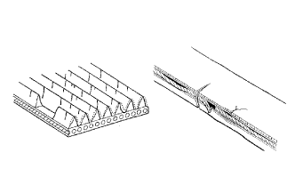
Check the belt for wear, cracks or other signs of damage.
If any of the following defects is found, replace the fan and generator V belt.
-
The belt is cracked.
-
The belt is worn out to the extent that the cords are exposed.
-
The belt has chunks missing from the ribs.
-
-
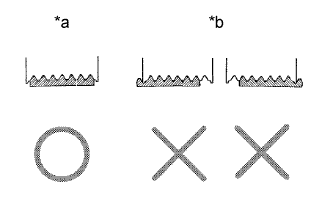
Text in Illustration *a CORRECT *b INCORRECT Check that the belt fits properly in the ribbed grooves.
Tech Tips
Check with your hand to confirm that the belt has not slipped out of the grooves on the bottom of the pulley. If it has slipped out, replace the fan and generator V belt. Install a new fan and generator V belt correctly.
-
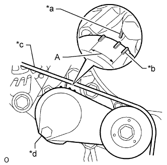
Text in Illustration *a Bracket Side Indicator *b Arm Side Indicator *c Fan and Generator V Belt *d V-ribbed belt tensioner assembly Check that the tensioner indicator mark is within range A shown in the illustration.
If the mark is not within range A, replace the fan and generator V belt.
Tech Tips
If a new belt has been installed, check that the tensioner indicator mark is within range A.
-
-
INSPECT GENERATOR WIRING
-
Check that the generator wiring is in good condition.
-
-
LISTEN FOR ABNORMAL NOISE FROM GENERATOR ASSEMBLY
-
Check that the generator assembly does not emit any abnormal noise while the engine is running.
-
-
INSPECT CHARGE WARNING LIGHT CIRCUIT
-
Turn the ignition switch to ON. Check that the charge warning light comes on.
-
Start the engine and check that the light goes off. If the light does not operate as specified, troubleshoot the charge warning light circuit.
-
-
INSPECT CHARGING CIRCUIT WITHOUT LOAD
-
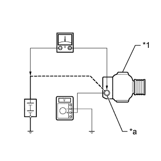
Text in Illustration *1 Generator *a Terminal B Connect a voltmeter and ammeter to the charging circuit as follows:
Tech Tips
If a battery/generator tester is available, connect the tester to the charging circuit according to the manufacturer's instructions.
-
Disconnect the wire from terminal B of the generator assembly and connect it to the negative (-) lead of the ammeter.
-
Connect the positive (+) lead of the ammeter to terminal B of the generator assembly.
-
Connect the positive (+) lead of the voltmeter to terminal B of the generator assembly.
-
Ground the negative (-) lead of the voltmeter.
-
-
Check the charging circuit.
-
Keep the engine speed at 2000 rpm. Check the reading on the ammeter and voltmeter.
Standard current 10 A or higher Standard voltage 10.275 to 16.25 V If the results are not as specified, replace the generator assembly.
Tech Tips
If the battery is not fully charged, the ammeter reading may be more than the standard current.
-
-
-
CHECK CHARGING CIRCUIT WITH LOAD
-
With the engine running at 2000 rpm, turn on the high beam headlights and turn the heater blower switch to the HI position.
-
Check the reading on the ammeter.
Standard current 30 A or higher If the ammeter reading is less than the standard current, replace the generator assembly.
Tech Tips
-
If the battery is fully charged, the ammeter reading may be less than the standard current.
-
In this case, increase electrical load by operating equipment such as the wiper motor and rear window defogger. Then, recheck the reading on the ammeter.
-
-