STARTER (for 1.6 kW Type) REASSEMBLY
-
INSTALL STARTER CENTER BEARING CLUTCH SUB-ASSEMBLY
-
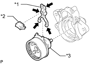
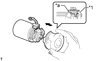
Text in Illustration *1 Starter Pinion Drive Lever *2 Rubber Plate *3 Starter Center Bearing Clutch Sub-assembly 
High-temperature Grease Apply high-temperature grease to the starter pinion drive lever as shown in the illustration.
-
Install the starter center bearing clutch sub-assembly, rubber plate and starter pinion drive lever to the starter drive housing assembly.
-
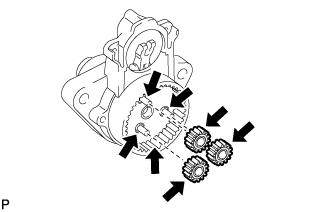
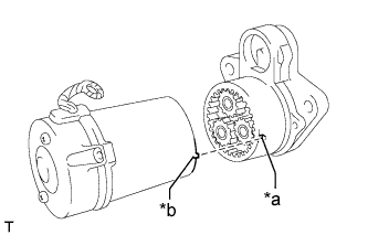
Apply high-temperature grease to the planetary gears and pins of the starter center bearing clutch sub-assembly as shown in the illustration.
Text in Illustration High-temperature Grease -
Install the 3 planetary gears to the starter center bearing clutch sub-assembly.
-
-
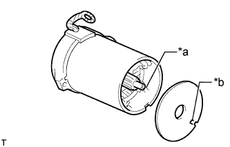
INSTALL STARTER ARMATURE ASSEMBLY
-
Install the starter armature assembly to the starter yoke assembly.
Note
The magnet of the starter yoke assembly may attract the starter armature assembly when the starter commutator end frame assembly is installed, causing the magnet to break.
-
-
INSTALL STARTER BRUSH HOLDER ASSEMBLY
-
Install the starter brush holder assembly to the starter yoke assembly.
-
Connect the 4 brushes to the starter brush holder assembly.
-
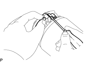
Using a screwdriver, hold back the spring.
-
Connect the brush to the starter brush holder assembly.
-
-
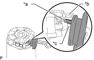
Text in Illustration *a Grommet *b Brush Holder Plate Negative (-) Side *c Motor Lead Line Positive (+) Side Insert a grommet between the positive (+) side of the motor lead line and the negative (-) side of the brush holder plate.
-
Text in Illustration *1 Starter Commutator End Frame Assembly *a Rubber Part Align the rubber part of the starter yoke assembly with the groove of the starter commutator end frame assembly.
-
Install the starter commutator end frame assembly with the 2 screws.
- Torque:
- 1.5 N*m { 15 kgf*cm, 13 in.*lbf }
-
-
INSTALL STARTER YOKE ASSEMBLY
-
Install the starter armature plate to the starter yoke assembly.
-
Text in Illustration *a Protrusion *b Notch Check that the notch of the starter armature plate fits over the protrusion of the starter yoke assembly.
-
Text in Illustration *a Notch *b Protrusion Align the protrusion of the starter yoke assembly with the notches inside the starter drive housing assembly and insert the starter yoke assembly into the starter drive housing assembly.
-
Using a T25 "TORX" socket wrench, install the starter drive housing assembly with the 2 through bolts.
- Torque:
- 6.0 N*m { 61 kgf*cm, 53 in.*lbf }
-
-
INSTALL MAGNET STARTER SWITCH ASSEMBLY
-
Apply high-temperature grease to the plunger hook of the magnet starter switch assembly.
-
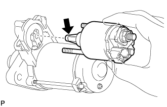
Hang the plunger of the magnet starter switch assembly on the starter pinion drive lever from the upper side.
Text in Illustration High-temperature Grease -
Install the magnet starter switch assembly with the 2 nuts.
- Torque:
- 7.5 N*m { 76 kgf*cm, 66 in.*lbf }
-
Connect the lead wire to terminal C with the nut.
- Torque:
- 10 N*m { 102 kgf*cm, 7 ft.*lbf }
-