STARTER (for 1.6 kW Type) INSPECTION
-
INSPECT STARTER ARMATURE ASSEMBLY
-
Check the commutator for dirt and/or burns on the surface.
If the surface is dirty or burnt, correct it with 400-grit sandpaper or a lathe.
-
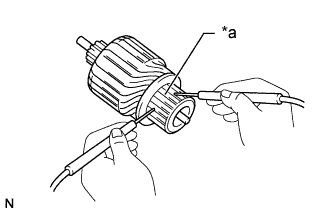
Text in Illustration *a Segment Inspect the commutator for an open circuit.
-
Measure the resistance according to the value(s) in the table below.
Standard Resistance Tester Connection Condition Specified Condition Segment - Segment Always Below 1 Ω If the result is not as specified, replace the starter armature assembly.
-
-
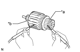
Text in Illustration *a Segment *b Armature Coil Core Inspect the commutator for a short circuit.
-
Measure the resistance according to the value(s) in the table below.
Standard Resistance Tester Connection Condition Specified Condition Segment - Armature coil core Always 10 kΩ or higher If the result is not as specified, replace the starter armature assembly.
-
-
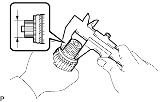
Using a vernier caliper, measure the commutator diameter.
Standard diameter 29.0 mm (1.14 in.) Minimum diameter 28.0 mm (1.10 in.) If the diameter is less than the minimum, replace the starter armature assembly.
-
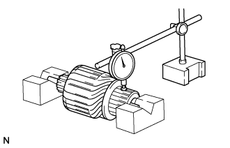
Check the commutator circle runout.
-
Place the shaft of the starter armature on V-blocks.
-
Using a dial indicator, measure the circle runout.
Maximum commutator runout 0.05 mm (0.00197 in.) If the runout is more than the maximum, replace the starter armature assembly.
-
-
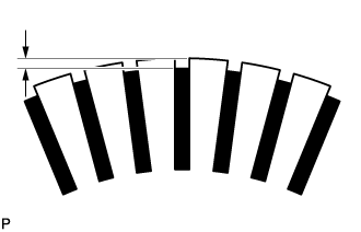
Measure the undercut depth of the commutator.
Standard undercut depth 0.7 mm (0.0276 in.) Minimum undercut depth 0.2 mm (0.00787 in.) If the undercut depth is less than the minimum, correct it with a hacksaw blade.
-
-
INSPECT STARTER BRUSH HOLDER ASSEMBLY
-
Using a vernier caliper, measure the brush length.
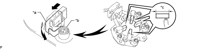
Text in Illustration *a Brush *b Spring *c Length - - Standard length 14.4 mm (0.567 in.) Minimum length 9.0 mm (0.354 in.) If the length is less than the minimum, replace the starter brush holder assembly and starter yoke assembly.
-
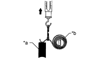
Text in Illustration *a Brush *b Brush Spring Inspect the load of the brush spring.
-
Take a pull scale reading immediately after the brush spring separates from the brush.
Standard spring load 16 to 20 N (1.7 to 2.0 kgf, 3.6 to 4.5 lbf) Minimum spring load 6.7 N (0.7 kgf, 1.5 lbf) If the load is less than the minimum, replace the starter brush holder assembly.
-
-
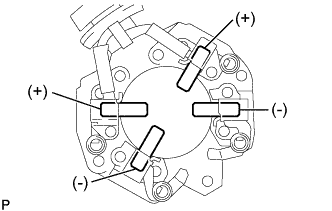
Inspect the insulation.
-
Measure the resistance according to the value(s) in the table below.
Standard Resistance Tester Connection Condition Specified Condition Positive brush holder - Negative brush holder Always 10 kΩ or higher If the result is not as specified, replace the starter brush holder assembly.
-
-
-
INSPECT STARTER CENTER BEARING CLUTCH SUB-ASSEMBLY
-
Check the gear teeth of the planetary gears and starter center bearing clutch for wear or damage.
If any planetary gear is damaged, replace the planetary gear assembly.
If any gear of the starter center bearing clutch is damaged, replace the starter center bearing clutch sub-assembly.
-
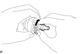
Check the movement of the clutch pinion gear.
Text in Illustration 
Free 
Lock
-
Rotate the clutch pinion gear clockwise and check that it turns freely.
-
Try to rotate the clutch pinion gear counterclockwise and check that it locks.
If the clutch pinion gear cannot be turned clockwise smoothly, or does not lock in the counterclockwise direction, replace the starter center bearing clutch sub-assembly.
-
-
-
INSPECT MAGNET STARTER SWITCH ASSEMBLY
-
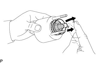
Push in the plunger and check that it returns quickly to its original position.
If the result is not as specified, replace the magnet starter switch assembly.
-
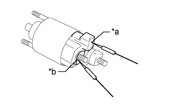
Text in Illustration *a Terminal 50 *b Terminal C Check the pull-in coil for an open circuit.
-
Measure the resistance according to the value(s) in the table below.
Standard Resistance Tester Connection Condition Specified Condition Terminal 50 - Terminal C Always Below 1 Ω If the result is not as specified, replace the magnet starter switch assembly.
-
-
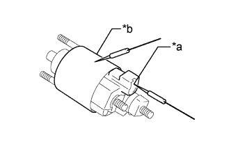
Text in Illustration *a Terminal 50 *b Switch Body Check the hold-in coil for an open circuit.
-
Measure the resistance according to the value(s) in the table below.
Standard Resistance Tester Connection Condition Specified Condition Terminal 50 - Switch body Always Below 2 Ω If the result is not as specified, replace the magnet starter switch assembly.
-
-