STARTER REASSEMBLY
-
INSTALL PLANETARY GEAR
-
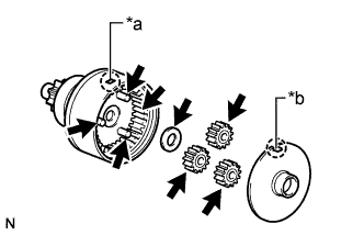
Text in Illustration *a Protrusion *b Cutout 
High-temperature Grease Apply high-temperature grease to the planetary gears, pin parts of the planetary shaft and inside of plate.
-
Install the plate washer and 3 planetary gears.
-
Align the cutout of the plate with the protrusion inside the starter center bearing clutch sub-assembly, and install the plate.
-
-
INSTALL STARTER CENTER BEARING CLUTCH SUB-ASSEMBLY
-
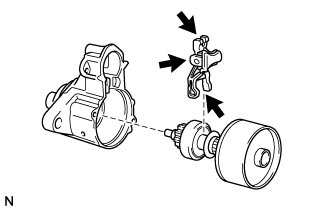
Apply high-temperature grease to the starter drive lever.
Text in Illustration High-temperature Grease -
Install the starter drive lever to the starter center bearing clutch sub-assembly.
-
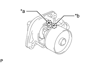
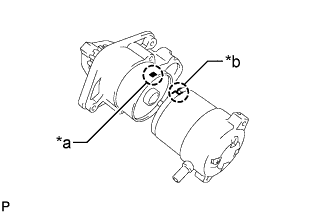
Text in Illustration *a Cutout *b Protrusion Align the protrusion of the starter center bearing clutch sub-assembly with the cutout of the starter drive housing assembly and install the starter drive lever and starter center bearing clutch sub-assembly.
-
-
INSTALL STARTER ARMATURE ASSEMBLY
-
Install the starter armature assembly to the starter yoke assembly.
-
-
INSTALL STARTER BRUSH HOLDER ASSEMBLY
-
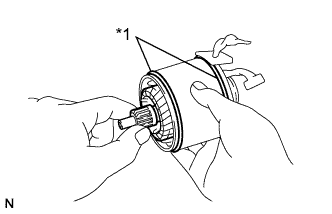
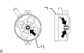
Text in Illustration *1 O-Ring Install 2 new O-rings to the starter yoke assembly.
-
Install the starter brush holder assembly to the starter armature assembly.
-
Install the 4 starter brushes to the starter brush holder assembly.
-
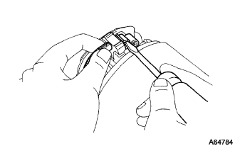
Using a screwdriver, pull back the spring.
Note
Check that the positive (+) lead wires are not grounded.
-
Install the brush to the starter brush holder assembly.
-
-
-
INSTALL STARTER COMMUTATOR END FRAME ASSEMBLY
-
Text in Illustration *1 Starter Commutator End Frame Assembly Spindle Oil Apply spindle oil to the bearing of the starter commutator end frame assembly.
-
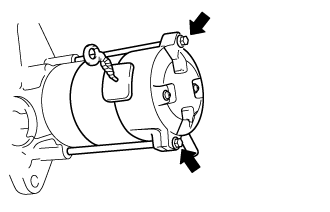
Install the starter commutator end frame assembly with the 2 screws.
- Torque:
- 1.5 N*m { 15 kgf*cm, 13 in.*lbf }
-
-
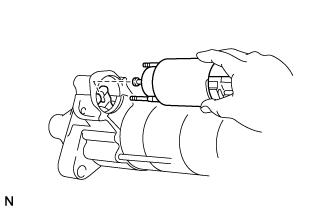
INSTALL STARTER YOKE ASSEMBLY
-
Text in Illustration *a Protrusion *b Cutout Align the cutout of the starter yoke assembly with the protrusion of the starter center bearing clutch sub-assembly.
-
Install the starter yoke assembly together with the starter armature assembly with the 2 through bolts.
- Torque:
- 5.9 N*m { 60 kgf*cm, 52 in.*lbf }
-
-
INSTALL MAGNET STARTER SWITCH ASSEMBLY
-
Install the plunger cover to the magnet starter switch assembly.
-
Attach the plunger of the magnet starter switch assembly to the starter drive lever from the upper side.
-
Install the magnet starter switch assembly with the 2 nuts.
- Torque:
- 8.3 N*m { 85 kgf*cm, 73 in.*lbf }
-
Connect the lead wire to terminal C with the nut.
- Torque:
- 9.8 N*m { 100 kgf*cm, 87 in.*lbf }
-