CAN COMMUNICATION SYSTEM TERMINALS OF ECU
Tech Tips
Operating the ignition switch, any switches or any doors triggers related ECU and sensor communication with the CAN, which causes resistance variation.
-
DISCONNECT CABLE FROM NEGATIVE BATTERY TERMINAL
-
Disconnect the cable from the negative (-) battery terminal before measuring the resistances of the CAN main wire and CAN branch wire.
CAUTION:
For vehicles with an airbag system:
Wait at least 90 seconds after disconnecting the cable from the negative (-) battery terminal to disable the SRS system.
Note
-
Before measuring the resistance, leave the vehicle for at least 1 minute and do not operate the ignition switch, any switches or any doors. If doors need to be opened in order to check connectors, open the doors and leave them open.
-
When disconnecting the cable, some systems need to be initialized after the cable is reconnected Click here.
-
-
-
JUNCTION CONNECTOR
-
No. 1 CAN Junction Connector
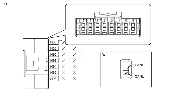
Text in Illustration *1 No. 1 CAN Junction Connector - - *a Front view of wire harness connector
(to No. 1 CAN Junction Connector)
- - No. 1 CAN Junction Connector Wiring Color Connect to H63-1 (CANH) B ECM H63-2 (CANL) W H66-1 (CANH) G Certification ECU (smart key ECU assembly)*1 H66-2 (CANL) W H90-1 (CANH) P Headlight leveling ECU assembly*2 H90-2 (CANL) W H93-1 (CANH) V Center airbag sensor assembly*3 H93-2 (CANL) W H94-1 (CANH) L Brake actuator assembly (skid control ECU)*4 H94-2 (CANL) W H95-1 (CANH) W Spiral cable sub-assembly (steering angle sensor)*5 H95-2 (CANL) R H96-1 (CANH) W No. 2 CAN junction connector H96-2 (CANL) B
-
*1: w/ Smart Entry and Start System
-
*2: for LED Headlight
-
*3: w/ Airbag System
-
*4: w/ ABS
-
*5: w/ VSC
-
-
No. 2 CAN Junction Connector
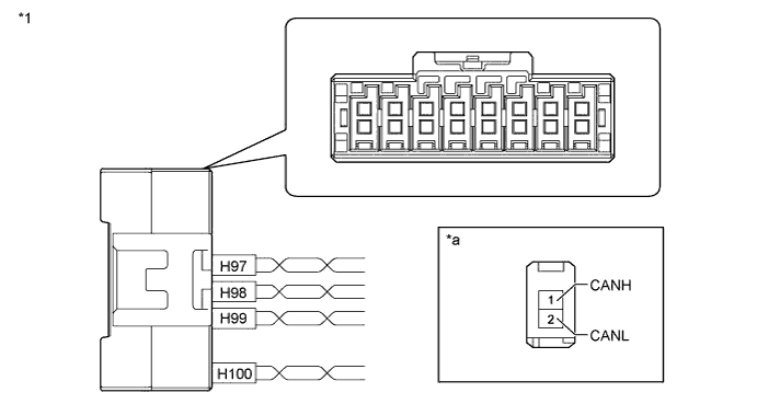
Text in Illustration *1 No. 2 CAN Junction Connector - - *a Front view of wire harness connector
(to No. 2 CAN Junction Connector)
- - No. 2 CAN Junction Connector Wiring Color Connect to H97-1 (CANH) R Air conditioning amplifier assembly* H97-2 (CANL) W H98-1 (CANH) Y DLC3 H98-2 (CANL) W H99-1 (CANH) B Combination meter assembly H99-2 (CANL) W H100-1 (CANH) W No. 1 CAN junction connector H100-2 (CANL) B
-
*: w/ Air Conditioning System, except 5L-E
-
-
-
CHECK DLC3
-
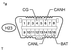
Text in Illustration *a Front view of DLC3 Disconnect the cable from the negative (-) battery terminal before measuring the resistances of the CAN main wire and CAN branch wire.
CAUTION:
For vehicles with an airbag system:
Wait at least 90 seconds after disconnecting the cable from the negative (-) battery terminal to disable the SRS system.
Note
-
Before measuring the resistance, leave the vehicle for at least 1 minute and do not operate the ignition switch, any switches or any doors. If doors need to be opened in order to check connectors, open the doors and leave them open.
-
When disconnecting the cable, some systems need to be initialized after the cable is reconnected Click here.
-
-
Measure the resistance according to the value(s) in the table below.
Terminal No. (Symbol) Wiring Color Switch Condition Specified Condition H23-6 (CANH) - H23-14 (CANL) Y - W Ignition switch off 54 to 69 Ω H23-6 (CANH) - H23-4 (CG) Y - W-B Ignition switch off 200 Ω or higher H23-14 (CANL) - H23-4 (CG) W - W-B Ignition switch off 200 Ω or higher H23-6 (CANH) - H23-16 (BAT) Y - B Ignition switch off 6 kΩ or higher H23-14 (CANL) - H23-16 (BAT) W - B Ignition switch off 6 kΩ or higher
-
-
CHECK ECM (for 1KD-FTV [w/ DPF])
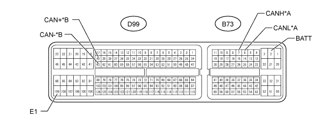
Text in Illustration *A for V1 Bus *B for Powertrain Bus
-
Disconnect the ECM connectors.
-
Measure the resistance according to the value(s) in the table below.
for V1 Bus Terminal No. (Symbol) Wiring Color Switch Condition Specified Condition B73-7 (CANH) - B73-6 (CANL) B - W Ignition switch off 108 to 132 Ω B73-7 (CANH) - D99-109 (E1) B - W-B Ignition switch off 200 Ω or higher B73-6 (CANL) - D99-109 (E1) W - W-B Ignition switch off 200 Ω or higher B73-7 (CANH) - B73-2 (BATT) B - W Ignition switch off 6 kΩ or higher B73-6 (CANL) - B73-2 (BATT) W - W Ignition switch off 6 kΩ or higher for Powertrain Bus Terminal No. (Symbol) Wiring Color Switch Condition Specified Condition D99-40 (CAN+) - D99-63 (CAN-) L - Y Ignition switch off 108 to 132 Ω D99-40 (CAN+) - D99-109 (E1) L - W-B Ignition switch off 200 Ω or higher D99-63 (CAN-) - D99-109 (E1) Y - W-B Ignition switch off 200 Ω or higher D99-40 (CAN+) - B73-2 (BATT) L - W Ignition switch off 6 kΩ or higher D99-63 (CAN-) - B73-2 (BATT) Y - W Ignition switch off 6 kΩ or higher
-
-
CHECK ECM (for 1KD-FTV [w/o DPF])

Text in Illustration *A for V1 Bus *B for Powertrain Bus
-
Disconnect the ECM connectors.
-
Measure the resistance according to the value(s) in the table below.
for V1 Bus Terminal No. (Symbol) Wiring Color Switch Condition Specified Condition B72-7 (CANH) - B72-6 (CANL) B - W Ignition switch off 108 to 132 Ω B72-7 (CANH) - D98-109 (E1) B - W-B Ignition switch off 200 Ω or higher B72-6 (CANL) - D98-109 (E1) W - W-B Ignition switch off 200 Ω or higher B72-7 (CANH) - B72-2 (BATT) B - W Ignition switch off 6 kΩ or higher B72-6 (CANL) - B72-2 (BATT) W - W Ignition switch off 6 kΩ or higher for Powertrain Bus Terminal No. (Symbol) Wiring Color Switch Condition Specified Condition D98-40 (CAN+) - D98-63 (CAN-) L - Y Ignition switch off 108 to 132 Ω D98-40 (CAN+) - D98-109 (E1) L - W-B Ignition switch off 200 Ω or higher D98-63 (CAN-) - D98-109 (E1) Y - W-B Ignition switch off 200 Ω or higher D98-40 (CAN+) - B72-2 (BATT) L - W Ignition switch off 6 kΩ or higher D98-63 (CAN-) - B72-2 (BATT) Y - W Ignition switch off 6 kΩ or higher
-
-
CHECK ECM (for 2KD-FTV)
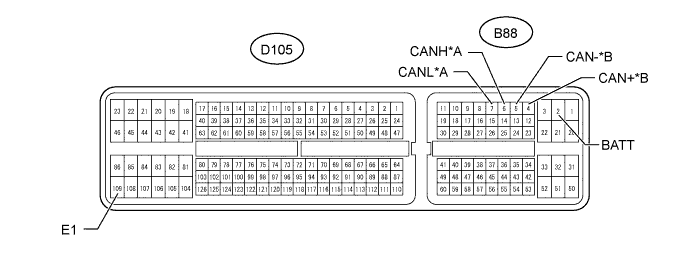
Text in Illustration *A for V1 Bus *B for Powertrain Bus
-
Disconnect the ECM connectors.
-
Measure the resistance according to the value(s) in the table below.
for V1 Bus Terminal No. (Symbol) Wiring Color Switch Condition Specified Condition B88-6 (CANH) - B88-7 (CANL) B - W Ignition switch off 108 to 132 Ω B88-6 (CANH) - D105-109 (E1) B - BR Ignition switch off 200 Ω or higher B88-7 (CANL) - D105-109 (E1) W - BR Ignition switch off 200 Ω or higher B88-6 (CANH) - B88-2 (BATT) B - W Ignition switch off 6 kΩ or higher B88-7 (CANL) - B88-2 (BATT) W - W Ignition switch off 6 kΩ or higher for Powertrain Bus Terminal No. (Symbol) Wiring Color Switch Condition Specified Condition B88-4 (CAN+) - B88-5 (CAN-) L - Y Ignition switch off 108 to 132 Ω B88-4 (CAN+) - D105-109 (E1) L - BR Ignition switch off 200 Ω or higher B88-5 (CAN-) - D105-109 (E1) Y - BR Ignition switch off 200 Ω or higher B88-4 (CAN+) - B88-2 (BATT) L - W Ignition switch off 6 kΩ or higher B88-5 (CAN-) - B88-2 (BATT) Y - W Ignition switch off 6 kΩ or higher
-
-
CHECK ECM (for 1GD-FTV)
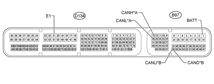
Text in Illustration *A for V1 Bus *B for Local Bus
-
Disconnect the ECM connectors.
-
Measure the resistance according to the value(s) in the table below.
for V1 Bus Terminal No. (Symbol) Wiring Color Switch Condition Specified Condition B97-13 (CANH) - B97-26 (CANL) B - W Ignition switch off 108 to 132 Ω B97-13 (CANH) - D134-21 (E1) B - W-B Ignition switch off 200 Ω or higher B97-26 (CANL) - D134-21 (E1) W - W-B Ignition switch off 200 Ω or higher B97-13 (CANH) - B97-1 (BATT) B - W Ignition switch off 6 kΩ or higher B97-26 (CANL) - B97-1 (BATT) W - W Ignition switch off 6 kΩ or higher for Local Bus Terminal No. (Symbol) Wiring Color Switch Condition Specified Condition B97-41 (CANU) - B97-56 (CAND) L - Y Ignition switch off 108 to 132 Ω B97-41 (CANU) - D134-21 (E1) L - W-B Ignition switch off 200 Ω or higher B97-56 (CAND) - D134-21 (E1) Y - W-B Ignition switch off 200 Ω or higher B97-41 (CANU) - B97-1 (BATT) L - W Ignition switch off 6 kΩ or higher B97-56 (CAND) - B97-1 (BATT) Y - W Ignition switch off 6 kΩ or higher
-
-
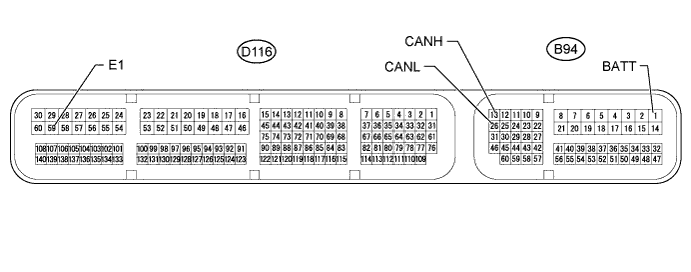
CHECK ECM (for 1TR-FE, 2TR-FE [w/ Dual VVT-i])
-
Disconnect the ECM connectors.
-
Measure the resistance according to the value(s) in the table below.
Terminal No. (Symbol) Wiring Color Switch Condition Specified Condition B94-13 (CANH) - B94-26 (CANL) B - W Ignition switch off 108 to 132 Ω B94-13 (CANH) - D116-59 (E1) B - W-B Ignition switch off 200 Ω or higher B94-26 (CANL) - D116-59 (E1) W - W-B Ignition switch off 200 Ω or higher B94-13 (CANH) - B94-1 (BATT) B - W Ignition switch off 6 kΩ or higher B94-26 (CANL) - B94-1 (BATT) W - W Ignition switch off 6 kΩ or higher
-
-
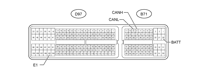
CHECK ECM (for 2TR-FE [w/o Dual VVT-i])
-
Disconnect the ECM connectors.
-
Measure the resistance according to the value(s) in the table below.
Terminal No. (Symbol) Wiring Color Switch Condition Specified Condition B71-8 (CANH) - B71-9 (CANL) B - W Ignition switch off 108 to 132 Ω B71-8 (CANH) - D97-105 (E1) B - W-B Ignition switch off 200 Ω or higher B71-9 (CANL) - D97-105 (E1) W - W-B Ignition switch off 200 Ω or higher B71-8 (CANH) - B71-20 (BATT) B - W Ignition switch off 6 kΩ or higher B71-9 (CANL) - B71-20 (BATT) W - W Ignition switch off 6 kΩ or higher
-
-
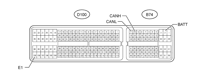
CHECK ECM (for 5L-E)
-
Disconnect the ECM connectors.
-
Measure the resistance according to the value(s) in the table below.
Terminal No. (Symbol) Wiring Color Switch Condition Specified Condition B74-10 (CANH) - B74-11 (CANL) B - W Ignition switch off 108 to 132 Ω B74-10 (CANH) - D100-109 (E1) B - W-B Ignition switch off 200 Ω or higher B74-11 (CANL) - D100-109 (E1) W - W-B Ignition switch off 200 Ω or higher B74-10 (CANH) - B74-2 (BATT) B - W Ignition switch off 6 kΩ or higher B74-11 (CANL) - B74-2 (BATT) W - W Ignition switch off 6 kΩ or higher
-
-
CHECK COMBINATION METER ASSEMBLY

-
Disconnect the combination meter assembly connector.
-
Measure the resistance according to the value(s) in the table below.
Terminal No. (Symbol) Wiring Color Switch Condition Specified Condition H20-23 (CANH) - H20-22 (CANL) B - W Ignition switch off 108 to 132 Ω H20-23 (CANH) - H20-21 (E1) B - W-B Ignition switch off 200 Ω or higher H20-22 (CANL) - H20-21 (E1) W - W-B Ignition switch off 200 Ω or higher H20-23 (CANH) - H20-1 (L) B - R Ignition switch off 6 kΩ or higher H20-22 (CANL) - H20-1 (L) W - R Ignition switch off 6 kΩ or higher
-
-
CHECK AIR CONDITIONING AMPLIFIER ASSEMBLY (w/ Air Conditioning System, except 5L-E)

-
Disconnect the air conditioning amplifier assembly connector.
-
Measure the resistance according to the value(s) in the table below.
Terminal No. (Symbol) Wiring Color Switch Condition Specified Condition H18-10 (CANH) - H18-11 (CANL) R - W Ignition switch off 54 to 69 Ω H18-10 (CANH) - H18-29 (GND) R - W-B Ignition switch off 200 Ω or higher H18-11 (CANL) - H18-29 (GND) W - W-B Ignition switch off 200 Ω or higher H18-10 (CANH) - H18-40 (B) R - W Ignition switch off 6 kΩ or higher H18-11 (CANL) - H18-40 (B) W - W Ignition switch off 6 kΩ or higher
-
-
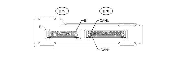
CHECK CERTIFICATION ECU (SMART KEY ECU ASSEMBLY) (w/ Smart Entry and Start System)
-
Disconnect the certification ECU (smart key ECU assembly) connectors.
-
Measure the resistance according to the value(s) in the table below.
Terminal No. (Symbol) Wiring Color Switch Condition Specified Condition B76-40 (CANH) - B76-18 (CANL) G - W Ignition switch off 54 to 69 Ω B76-40 (CANH) - B75-10 (E) G - W-B Ignition switch off 200 Ω or higher B76-18 (CANL) - B75-10 (E) W - W-B Ignition switch off 200 Ω or higher B76-40 (CANH) - B75-1 (+B) G - L Ignition switch off 6 kΩ or higher B76-18 (CANL) - B75-1 (+B) W - L Ignition switch off 6 kΩ or higher
-
-
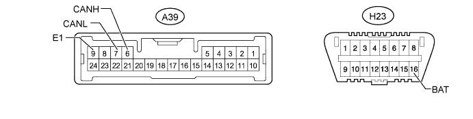
CHECK HEADLIGHT LEVELING ECU ASSEMBLY (for LED Headlight)
-
Disconnect the headlight leveling ECU assembly connector.
-
Measure the resistance according to the value(s) in the table below.
Terminal No. (Symbol) Wiring Color Switch Condition Specified Condition A39-6 (CANH) - A39-7 (CANL) P - W Ignition switch off 54 to 69 Ω A39-6 (CANH) - A39-9 (E1) P - W-B Ignition switch off 200 Ω or higher A39-7 (CANL) - A39-9 (E1) W - W-B Ignition switch off 200 Ω or higher A39-6 (CANH) - H23-16 (BAT) P - B Ignition switch off 6 kΩ or higher A39-7 (CANL) - H23-16 (BAT) W - B Ignition switch off 6 kΩ or higher
-
-
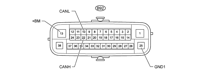
CHECK BRAKE ACTUATOR ASSEMBLY (SKID CONTROL ECU) (w/ VSC)
-
Disconnect the brake actuator assembly (skid control ECU) connector.
-
Measure the resistance according to the value(s) in the table below.
Terminal No. (Symbol) Wiring Color Switch Condition Specified Condition B92-22 (CANH) - B92-10 (CANL) L - W Ignition switch off 54 to 69 Ω B92-22 (CANH) - B92-25 (GND1) L - W-B Ignition switch off 200 Ω or higher B92-10 (CANL) - B92-25 (GND1) W - W-B Ignition switch off 200 Ω or higher B92-22 (CANH) - B92-13 (+BM) L - W Ignition switch off 6 kΩ or higher B92-10 (CANL) - B92-13 (+BM) W - W Ignition switch off 6 kΩ or higher
-
-
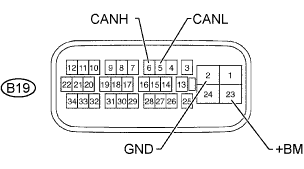
CHECK BRAKE ACTUATOR ASSEMBLY (SKID CONTROL ECU) (w/o VSC)
-
Disconnect the brake actuator assembly (skid control ECU) connector.
-
Measure the resistance according to the value(s) in the table below.
Terminal No. (Symbol) Wiring Color Switch Condition Specified Condition B19-6 (CANH) - B19-5 (CANL) L - W Ignition switch off 54 to 69 Ω B19-6 (CANH) - B19-2 (GND) L - W-B Ignition switch off 200 Ω or higher B19-5 (CANL) - B19-2 (GND) W - W-B Ignition switch off 200 Ω or higher B19-6 (CANH) - B19-23 (+BM) L - W Ignition switch off 6 kΩ or higher B19-5 (CANL) - B19-23 (+BM) W - W Ignition switch off 6 kΩ or higher
-
-
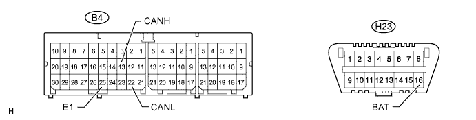
CHECK CENTER AIRBAG SENSOR ASSEMBLY (w/ Airbag System)
-
Disconnect the center airbag sensor assembly connector Click here.
-
Measure the resistance according to the value(s) in the table below.
Terminal No. (Symbol) Wiring Color Switch Condition Specified Condition B4-13 (CANH) - B4-22 (CANL) V - W Ignition switch off 54 to 69 Ω B4-13 (CANH) - B4-25 (E1) V - W-B Ignition switch off 200 Ω or higher B4-22 (CANL) - B4-25 (E1) W - W-B Ignition switch off 200 Ω or higher B4-13 (CANH) - H23-16 (BAT) V - B Ignition switch off 6 kΩ or higher B4-22 (CANL) - H23-16 (BAT) W - B Ignition switch off 6 kΩ or higher
-
-
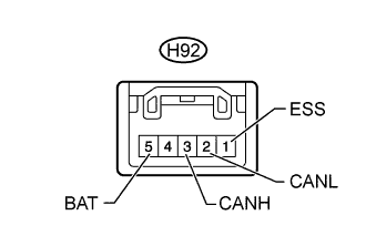
CHECK SPIRAL CABLE SUB-ASSEMBLY (STEERING ANGLE SENSOR) (w/ VSC)
-
Disconnect the spiral cable sub-assembly (steering angle sensor) connector.
-
Measure the resistance according to the value(s) in the table below.
Terminal No. (Symbol) Wiring Color Switch Condition Specified Condition H92-3 (CANH) - H92-2 (CANL) W - R Ignition switch off 54 to 69 Ω H92-3 (CANH) - H92-1 (ESS) W - W-B Ignition switch off 200 Ω or higher H92-2 (CANL) - H92-1 (ESS) R - W-B Ignition switch off 200 Ω or higher H92-3 (CANH) - H92-5 (BAT) W - W Ignition switch off 6 kΩ or higher H92-2 (CANL) - H92-5 (BAT) R - W Ignition switch off 6 kΩ or higher
-
-
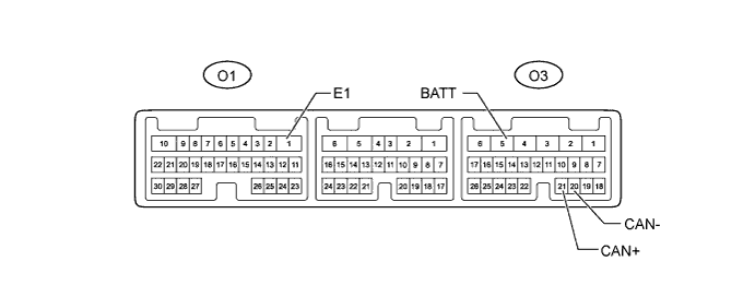
CHECK TRANSMISSION CONTROL ECU ASSEMBLY (for 1KD-FTV, 2KD-FTV and Automatic Transmission)
-
Disconnect the transmission control ECU assembly connectors.
-
Measure the resistance according to the value(s) in the table below.
Terminal No. (Symbol) Wiring Color Switch Condition Specified Condition O3-21 (CAN+) - O3-20 (CAN-) L - Y Ignition switch off 108 to 132 Ω O3-21 (CAN+) - O1-1 (E1) L - W-B Ignition switch off 200 Ω or higher O3-20 (CAN-) - O1-1 (E1) Y - W-B Ignition switch off 200 Ω or higher O3-21 (CAN+) - O3-5 (BATT) L - B Ignition switch off 6 kΩ or higher O3-20 (CAN-) - O3-5 (BATT) Y - B Ignition switch off 6 kΩ or higher
-