BACK DOOR ADJUSTMENT

-
INSPECT BACK DOOR
-
Check that the clearance of areas A to P are within the standard range.

Standard Area Measurement Area Measurement A 21.4 mm (0.843 in.) I 21.5 mm (0.847in.) B 5.2 mm (0.205 in.) J 5.2mm (0.205in.) C 10.1 mm (0.398 in.) K 10.4 mm (0.409in.) D 110.9 mm (4.366 in.) L 111 mm (4.37in.) E 20 mm (0.787 in.) M 18 mm (0.709in.) F 5.2 mm (0.205 in.) N 5.2 mm (0.205in.) G 10.2 mm (0.402 in.) O 10.4 mm (0.409in.) H 110.9 mm (4.366in.) P 111 mm (4.37in.)
-
-
ADJUST BACK DOOR
-
Disconnect the cable from negative (-) battery terminal from the battery.
CAUTION:
Work must be started at least 90 seconds after the ignition switch is turned off and the negative(-) terminal cable is disconnected from the battery. (The SRS is equipped with a back-up power source. If work is started within 90 seconds of disconnecting the cable from the negative (-) battery terminal and turning the ignitionswitch off, the SRS may deploy.)
-
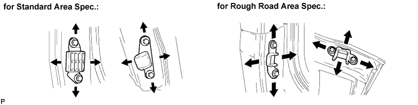
Loosen the bolts to adjust the back door upper up and down, side to side.
- Torque:
- 19 N*m { 194 kgf*cm, 14 ft.*lbf }
-
When adjusting the back door rear side to side, and the back door lock striker assembly, loosen the bolts until the striker can move. Lightly tap the striker with a brass bar for adjustment.
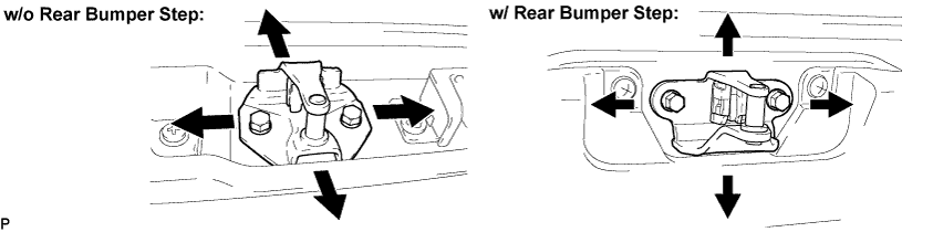
- Torque:
- 19 N*m { 194 kgf*cm, 14 ft.*lbf }
-
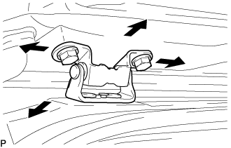
After completing fitting adjustment, confirm the position of the back door side female stopper and back door side male stopper.
- Torque:
- 7.5 N*m { 77 kgf*cm, 66 in.*lbf }
-
Connect the negative (-) terminal cable to the battery.
-
Initialize both systems.
-
Inspect the SRS warning light.
-