BACK DOOR DISASSEMBLY
-
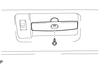
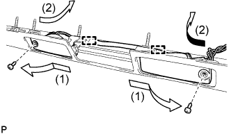
REMOVE OUTER UNDER REAR VIEW MIRROR ASSEMBLY (w/ Outer Under Rear View Mirror)
-
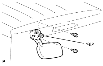
Remove the 3 screws, disengage the pin and remove the outer under rear view mirror.
Tech Tips
The screw <a> cannot be removed because it is integrated with the outer under view mirror.
-
-
REMOVE BACK DOOR SERVICE HOLE COVER (for Wide Body)
-
REMOVE UPPER BACK DOOR TRIM BOARD ASSEMBLY (w/o Rear Wiper)
-
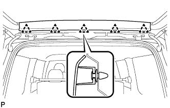
Detach the 5 clips and remove the upper back door trim board assembly.
-
-
REMOVE UPPER BACK DOOR TRIM BOARD ASSEMBLY (w/ Rear Wiper)
-
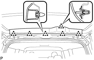
Detach the 6 clips and remove the upper back door trim board assembly.
-
Remove the remaining clips on the body, and reinstall them to the upper back door trim board assembly.
-
-
REMOVE BACK WINDOW GLASS HAMMER ASSEMBLY (w/ Hammer)
-
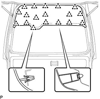
REMOVE UPPER BACK DOOR TRIM BOARD ASSEMBLY (for Wide Body)
-
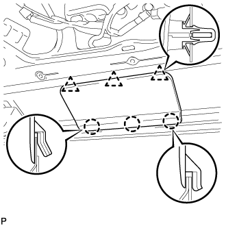
Detach the 18 clips and remove the upper back door trim board assembly.
-
Remove the remaining clips on the body, and reinstall them to the upper back door trim board assembly.
-
-
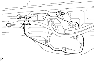
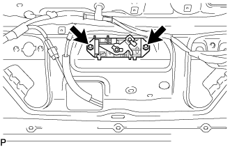
REMOVE QUARTER PANEL REINFORCEMENT BRACKET RH (w/ Hammer)
-
Detach the clamp.
-
Remove the 2 bolts.
-
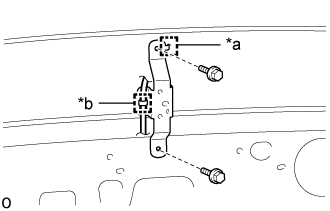
Text in Illustration *a Guide *b Clamp Detach the guide and remove the quarter panel reinforcement bracket RH.
-
-
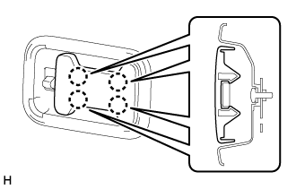
REMOVE REAR WIPER ARM AND BLADE ASSEMBLY (w/ Rear Wiper)
-
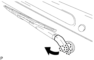
Disengage the 3 claws and separate the head cap as shown in the illustration.
-
Remove the rear wiper arm nut and rear wiper arm and blade assembly.
-
-
REMOVE REAR WIPER SHAFT COVER (w/ Rear Wiper)
-
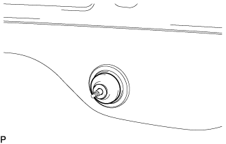
Remove the rear wiper shaft cover.
-
-
REMOVE NO. 1 REAR WIPER LINK PIVOT WASHER (w/ Rear Wiper)
-
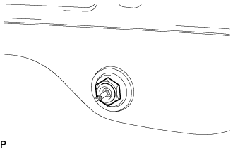
Using the socket wrench (27 mm), remove the lock nut and rear No.1 wiper link pivot washer.
Note
Do not damage the glass.
-
-
REMOVE REAR WIPER MOTOR ASSEMBLY (w/ Rear Wiper)
-
Disconnect the connector and remove the clamp.
-
Remove the 3 bolts and rear wiper motor and grommet as a unit.
-
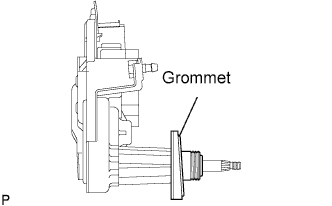
Remove the grommet from the rear wiper motor.
-
-
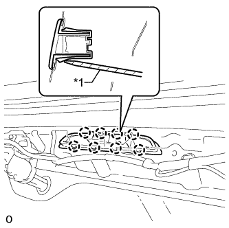
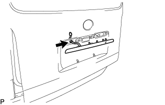
REMOVE HIGH MOUNTED STOP LIGHT ASSEMBLY (w/ High Mounted Stop Light)
-
Disconnect the connector.
-
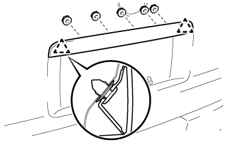
Using a screwdriver, detach the 8 claws and remove the high mounted stop light assembly.
Text in Illustration *1 Protective Tape Tech Tips
Tape the screwdriver tip before use.
-
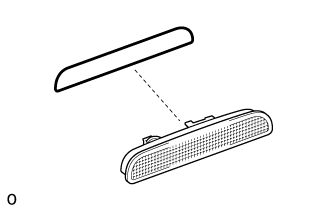
Remove the gasket from the high mounted stop light assembly.
Note
When removing the high mounted stop light assembly, replace the gasket with a new one.
-
-
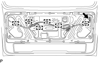
REMOVE NO. 3 BACK DOOR WIRE
-
Disconnect the connectors.
-
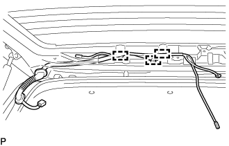
Detach the 3 clamps and remove the No. 3 back door wire.
-
-
REMOVE NO. 1 REAR WINDOW WIRE
-
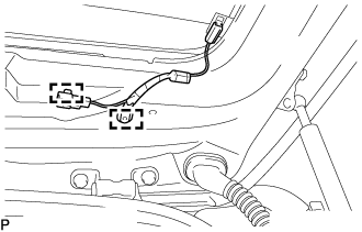
Detach the 2 clamps and remove the No. 1 rear window wire.
-
-
REMOVE BACK DOOR INSIDE HANDLE COVER (w/ Cover)
-
Detach the 4 claws and remove the back door inside handle cover.
-
-
REMOVE BACK DOOR INSIDE HANDLE ASSEMBLY (w/ Back Door Inside Handle)
-
Remove the screw and the back door inside handle assembly.
-
-
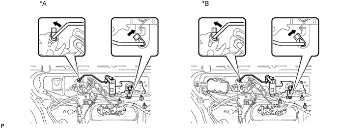
REMOVE BACK DOOR INSIDE HANDLE BEZEL (w/ Back Door Inside Handle Bezel)
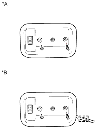
Text in Illustration *A w/o Illumination *B w/ Illumination
-
w/o Illumination:
-
Remove the 2 screws and the back door inside handle bezel.
-
-
w/ Illumination:
-
Remove the 2 screws and the back door inside handle bezel.
-
Disconnect the connector.
-
-
-
REMOVE BACK DOOR PULL STRAP (w/ Strap)
-
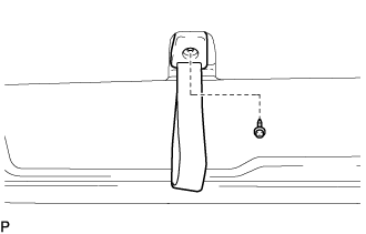
Remove the screw and back door pull strap.
-
-
REMOVE BACK DOOR TRIM BOARD (for Board)
-
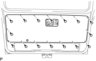
Using a clip remover, remove the 16 clips and the back door trim board.
-
-
REMOVE BACK DOOR TRIM BOARD (for Molded Door Trim)
-
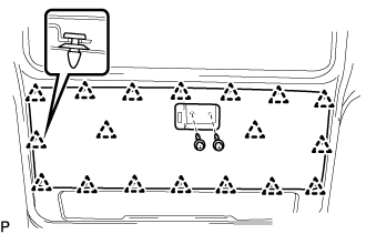
Remove the 2 screws.
-
Using a clip remover, remove the 18 clips and the back door trim board.
-
-
REMOVE BACK DOOR INSIDE HANDLE ASSEMBLY (w/ Back Door Inside Handle)
-
Disconnect the link.
-
Remove the 3 screws and the back door inside handle assembly.
Text in Illustration *A w/o Power Door Lock *B w/ Power Door Lock
-
-
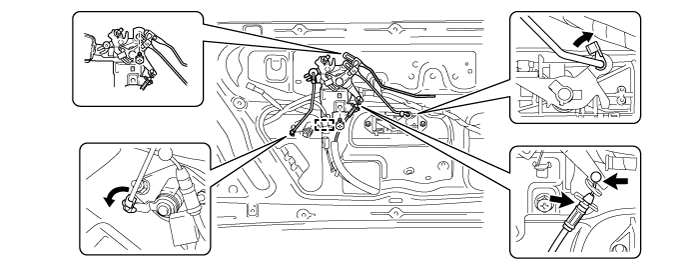
REMOVE BACK DOOR REMOTE CONTROL ASSEMBLY (w/o Power Door Lock)
-
Disconnect the wire and link.
-
Detach the clamp.
-
Remove the 2 screws and the back door remote control assembly.
-
-
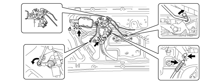
REMOVE BACK DOOR REMOTE CONTROL ASSEMBLY (w/ Power Door Lock)
-
Disconnect the wire and link.
-
Detach the 2 clamps.
-
Remove the 3 screws and the back door remote control assembly.
-
-
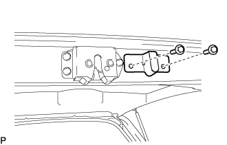
REMOVE BACK DOOR LOCK CYLINDER ASSEMBLY
-
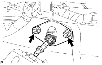
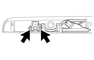
Remove the 2 nuts and back door lock cylinder assembly.
-
-
REMOVE BACK DOOR OUTSIDE HANDLE
-
Remove the 2 nuts and the back door outside handle.
-
-
REMOVE BACK DOOR OUTSIDE GARNISH
-
w/ Smart Entry and Start System:
-
Disconnect the 2 connectors.
-
-
w/o Smart Entry and Start System:
-
Disconnect the connector.
-
-
Remove the 5 nuts.
-
Detach the 2 clips and remove the back door outside garnish.
-
Remove the grommet.
-
-
REMOVE LICENSE PLATE LIGHT ASSEMBLY (w/ Smart Entry and Start System)
-
Remove the 2 screws.
-
Remove the 2 screws and detach the 2 wire harness clamps.
-
Remove the 2 license plate light assemblies (smart switch) from the back door outside garnish in the order shown in the illustration.
-
-
REMOVE DOOR ELECTRICAL KEY SWITCH COVER (w/ Smart Entry and Start System)
-
Remove the door electrical key switch cover.
-
-
REMOVE LICENSE PLATE LIGHT ASSEMBLY (w/o Smart Entry and Start System)
-
Remove the 2 screws and detach the 2 wire harness clamps.
-
Remove the 2 license plate lights from the back door outside garnish in the order shown in the illustration.
-
-
REMOVE TELEVISION CAMERA ASSEMBLY (w/ Rear View Monitor System)
-
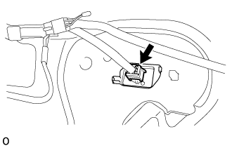
Disconnect the connector.
-
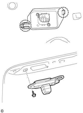
Remove the screw.
-
Detach the 2 claws and television camera assembly.
-
-
REMOVE BACK DOOR CLOSER RELAY (w/ Easy Closer)
-
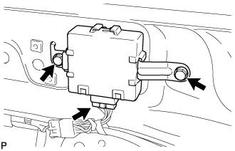
Disconnect the connector.
-
Remove the 2 bolts and back door closer relay.
-
-
REMOVE BACK DOOR CLOSER COVER (w/ Easy Closer)
-
Detach the 3 clips and 3 claws and remove the back closer cover.
-
-
REMOVE BACK DOOR STOPPER BRACKET SUB-ASSEMBLY (for Rough Road Area Spec)
-
Remove the 2 bolts and the back door stopper bracket sub-assembly.
-
-
REMOVE BACK DOOR LOCK PROTECTOR (w/ Rear Bumper Step)
-
Remove the screw and the back door lock protector.
-
-
REMOVE PIN HOLD CLIP (w/ Easy Closer)
-
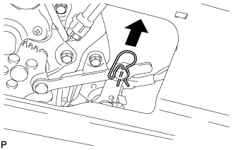
Remove the pin hold clip.
-
-
REMOVE BACK DOOR LOCK ASSEMBLY (w/ Easy Closer)
-
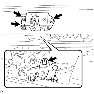
Remove the 4 bolts and the back door lock assembly.
-
-
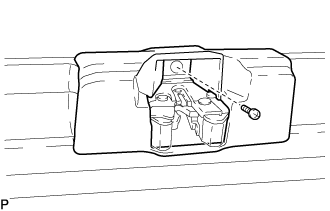
REMOVE BACK DOOR CLOSER MOTOR ASSEMBLY (w/ Easy Closer)
-
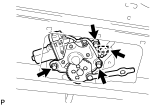
Disconnect the connector and detach the clamp.
-
Remove the 3 bolts and back door closer motor assembly.
-
-
REMOVE DOOR CONTROL MOTOR (w/ Easy Closer)
-
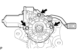
Using a T25 "TORX" driver, remove the 3 "TORX" screws and door control motor.
-
-
REMOVE BACK DOOR LOCK ASSEMBLY (w/o Easy Closer)
-
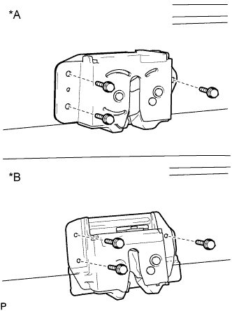
Text in Illustration *A w/o Rear Bumper Step *B w/ Rear Bumper Step Remove the 3 bolts and the back door lock assembly.
-
-
REMOVE NO. 2 BACK DOOR WIRE
-
Remove the bolt.
-
Detach the 6 clamps and remove the No. 2 back door wire.
-
-
REMOVE BACK DOOR STOPPER LH
-
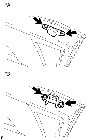
Text in Illustration *A for Standard Area Spec *B for Rough Road Area Spec Remove the 2 bolts and the back door stopper LH.
-
-
REMOVE BACK DOOR STOPPER RH
Tech Tips
Use the same procedure for the LH side.
-
REMOVE BACK DOOR STAY ASSEMBLY LH
-
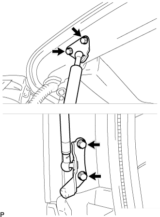
Remove the 4 bolts and the back door stay assembly LH.
Note
Remove the back door stay while holding the back door to prevent it from moving down.
-
-
REMOVE BACK DOOR STAY ASSEMBLY RH
Tech Tips
Use the same procedure for the LH side.