BACK DOOR CLOSER SYSTEM TERMINALS OF ECU
-
CHECK BACK DOOR CLOSER RELAY
-
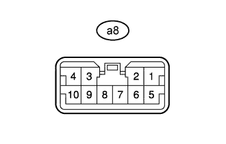
Disconnect the a8 back door closer relay connector.
-
Measure the resistance and voltage according to the value(s) in the table below.
Terminal No. (Symbol) Wiring Color Terminal Description Condition Specified Condition a8-7 (E) - Body ground W-B - Body ground Ground Always Below 1 Ω a8-5 (L) - Body ground W - Body ground Battery power supply Always 11 to 14 V -
Reconnect the a8 back door closer relay connector.
-
Measure the voltage according to the value(s) in the table below.
Terminal No. (Symbol) Wiring Color Terminal Description Condition Specified Condition a8-3 (P/W) - a8-7 (E) W - W-B Back door lock assembly (half latch switch) signal circuit Back door open → back door ajar → back door fully closed Below 1 V → 11 to 14 V → 11 to 14 V a8-9 (SIG) - a8-7 (E) V - W-B Back door lock assembly (latch switch) signal circuit Back door open → back door ajar → back door fully closed Below 1 V → 11 to 14 V → Below 1 V a8-2 (UL1) - a8-7 (E) L - W-B Back door lock assembly (back door lock motor) circuit Back door open → back door closer motor assembly normal operation → back door closer motor assembly return operation → back door closer motor assembly operation stop Below 1 V → Below 1 V → 11 to 14 V → Below 1 V → Below 1 V a8-1 (UL2) - a8-7 (E) R - W-B Back door lock assembly (back door lock motor) circuit Back door open → back door closer motor assembly normal operation → back door closer motor assembly return operation → back door closer motor assembly operation stop Below 1 V → Below 1 V → Below 1 V → 11 to 14 V → Below 1 V a8-10 (LSWD) - a8-7 (E) GR - W-B Back door lock assembly (initial position switch) signal circuit Back door open → back door closer motor assembly operating → back door fully closed 11 to 14 V → Below 1 V → 11 to 14 V
-