SLIDE DOOR CLOSER SYSTEM Door Control Relay Power source Circuit
DESCRIPTION
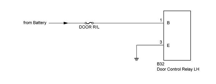
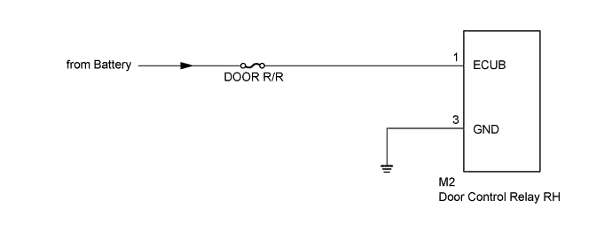
This circuit provides power to the door control relay LH*1 or door control relay RH*2.
-
*1: for LH Side
-
*2: for RH Side
WIRING DIAGRAM
-
for LH Side
-
for RH Side
INSPECTION PROCEDURE
Note
Inspect the fuses for circuits related to this system before performing the following inspection procedure.
PROCEDURE
-
CHECK DOOR CONTROL RELAY (POWER SOURCE)
-
Check the malfunctioning relay.
Result Result Proceed to Malfunction in LH side A Malfunction in RH side B
B 
CHECK HARNESS AND CONNECTOR (DOOR CONTROL RELAY RH - BATTERY AND BODY GROUND) Click here
A 
-
-
CHECK HARNESS AND CONNECTOR (DOOR CONTROL RELAY LH - BATTERY AND BODY GROUND)
-
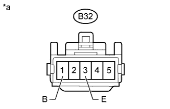
Text in Illustration *a Front view of wire harness connector
(to Door Control Relay LH)
Disconnect the door control relay LH connector.
-
Measure the resistance according to the value(s) in the table below.
Standard Resistance Tester Connection Condition Specified Condition B32-3 (E) - Body ground Always Below 1 Ω -
Measure the voltage according to the value(s) in the table below.
Standard Voltage Tester Connection Condition Specified Condition B32-1 (B) - Body ground Always 11 to 14 V
NG 
REPAIR OR REPLACE HARNESS OR CONNECTOR
OK 
PROCEED TO NEXT SUSPECTED AREA SHOWN IN PROBLEM SYMPTOMS TABLE Click here
-
-
CHECK HARNESS AND CONNECTOR (DOOR CONTROL RELAY RH - BATTERY AND BODY GROUND)
-
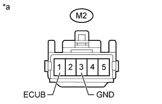
Text in Illustration *a Front view of wire harness connector
(to Door Control Relay RH)
Disconnect the door control relay RH connector.
-
Measure the resistance according to the value(s) in the table below.
Standard Resistance Tester Connection Condition Specified Condition M2-3 (GND) - Body ground Always Below 1 Ω -
Measure the voltage according to the value(s) in the table below.
Standard Voltage Tester Connection Condition Specified Condition M2-1 (ECUB) - Body ground Always 11 to 14 V
NG
REPAIR OR REPLACE HARNESS OR CONNECTOR
OK
PROCEED TO NEXT SUSPECTED AREA SHOWN IN PROBLEM SYMPTOMS TABLE Click here
-