SLIDE DOOR CLOSER SYSTEM Slide Door Closer Motor LH Circuit
DESCRIPTION
-
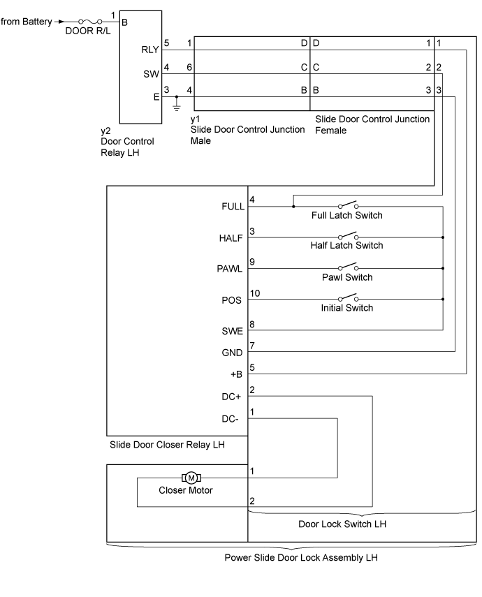
The slide door closer relay LH controls the power slide door lock assembly LH. In response to the output signals from the switches in the power slide door lock assembly LH, the slide door closer drives the closer motor.
w/o Power Slide Door
-
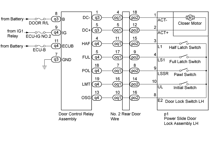
The door control relay assembly controls the power slide door lock assembly LH. In response to the output signals from the switches in the power slide door lock assembly LH, the slide door closer drives the closer motor.
w/ Power Slide Door
WIRING DIAGRAM
-
w/ Power Slide Door
-
w/o Power Slide Door
INSPECTION PROCEDURE
Note
Inspect the fuses for circuits related to this system before performing the following inspection procedure.
PROCEDURE
-
CHECK VEHICLE TYPE
-
Check vehicle type.
Result Result Proceed to w/o Power Slide Door A w/ Power Slide Door B
B 
INSPECT POWER SLIDE DOOR LOCK ASSEMBLY LH Click here
A 
-
-
INSPECT POWER SLIDE DOOR LOCK ASSEMBLY LH
-
Check the motor.
-
Remove the power slide door lock assembly LH Click here.
-
Inspect the power slide door lock assembly LH Click here.
-
-
Check the switches.
-
Remove the power slide door lock assembly LH Click here.
-
Inspect the power slide door lock assembly LH Click here.
Result Result Proceed to OK A NG (malfunctioning in motor) B NG (malfunctioning in switches) C -
B 
REPLACE POWER SLIDE DOOR LOCK ASSEMBLY LH Click here
C
REPLACE DOOR LOCK SWITCH LH
A 
PROCEED TO NEXT SUSPECTED AREA SHOWN IN PROBLEM SYMPTOMS TABLE Click here
-
-
INSPECT POWER SLIDE DOOR LOCK ASSEMBLY LH
-
Check the motor.
-
Remove the power slide door lock assembly LH Click here.
-
Inspect the power slide door lock assembly LH Click here.
-
-
Check the switches.
-
Remove the power slide door lock assembly LH Click here.
-
Inspect the power slide door lock assembly LH Click here.
Result Result Proceed to OK A NG (malfunctioning in motor) B NG (malfunctioning in switches) C -
B
REPLACE POWER SLIDE DOOR LOCK ASSEMBLY LH Click here
C
REPLACE DOOR LOCK SWITCH LH
A
-
-
INSPECT NO. 2 REAR DOOR WIRE
-
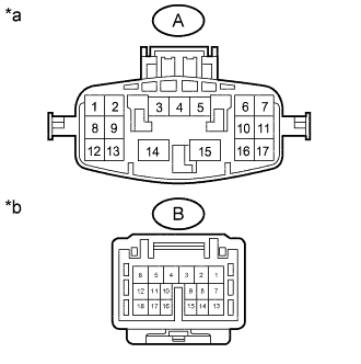
Text in Illustration *a No. 2 Rear Door Wire
(Door Control Relay Assembly Side)
*b No. 2 Rear Door Wire
(Power Slide Door Lock Assembly LH Side)
Disconnect the oq1 and po2 No. 2 rear door wire connectors.
-
Measure the resistance according to the value(s) in the table below.
Standard Resistance Tester Connection Condition Specified Condition A-4 - B-18 Always Below 1 Ω A-5 - B-12 Always Below 1 Ω A-7 - B-8 Always Below 1 Ω A-10 - B-16 Always Below 1 Ω A-11 - B-15 Always Below 1 Ω A-16 - B-14 Always Below 1 Ω A-17 - B-9 Always Below 1 Ω
NG
REPLACE NO. 2 REAR DOOR WIRE Click here
OK
-
-
CHECK HARNESS AND CONNECTOR (DOOR CONTROL RELAY ASSEMBLY - POWER SLIDE DOOR LOCK ASSEMBLY LH)
-
Disconnect the q3 and q4 door control relay assembly connectors.
-
Disconnect the p1 power slide door lock assembly LH connector.
-
Measure the resistance according to the value(s) in the table below.
Standard Resistance Tester Connection Condition Specified Condition q3-1 (DC-) - p1-1 (ACT-) Always Below 1 Ω q3-5 (DC+) - p1-2 (ACT+) Always Below 1 Ω q4-4 (HAF) - p1-3 (L1) Always Below 1 Ω q4-5 (FUL) - p1-4 (LS1) Always Below 1 Ω q4-18 (POL) - p1-9 (LSSR) Always Below 1 Ω q4-19 (LMT) - p1-10 (UL) Always Below 1 Ω q4-13 (OSG) - p1-8 (E2) Always Below 1 Ω q3-1 (DC-) or p1-1 (ACT-) - Body ground Always 10 kΩ or higher q3-5 (DC+) or p1-2 (ACT+) - Body ground Always 10 kΩ or higher q4-4 (HAF) or p1-3 (L1) - Body ground Always 10 kΩ or higher q4-5 (FUL) or p1-4 (LS1) - Body ground Always 10 kΩ or higher q4-18 (POL) or p1-9 (LSSR) - Body ground Always 10 kΩ or higher q4-19 (LMT) or p1-10 (UL) - Body ground Always 10 kΩ or higher q4-13 (OSG) or p1-8 (E2) - Body ground Always 10 kΩ or higher
NG
REPAIR OR REPLACE HARNESS OR CONNECTOR
OK
PROCEED TO NEXT SUSPECTED AREA SHOWN IN PROBLEM SYMPTOMS TABLE Click here
-