SLIDE DOOR CLOSER SYSTEM TERMINALS OF ECU
-
CHECK SLIDE DOOR CLOSER RELAY LH (w/o Power Slide Door)
-
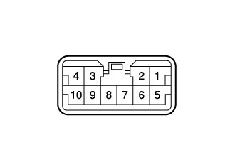
Disconnect the slide door closer relay LH connector.
-
Measure the voltage and resistance according to the value(s) in the table below.
Terminal No. (Symbol) Wiring Color Terminal Description Condition Specified Condition 7 (GND) - Body ground B - Body ground Ground Slide door LH fully open → fully close Below 1 Ω 5 (+B) - Body ground R - Body ground Battery power supply Slide door LH fully open → fully close Below 1 V → 11 to 14 V 3 (HALF) - 8 (SWE) Y - L Latch switch condition Slide door LH open → halfway position Below 1 Ω → 10 kΩ or higher 4 (FULL) - 8 (SWE) B - L Latch switch condition Slide door LH open → fully close Below 1 Ω → 10 kΩ or higher 9 (PAWL) - 8 (SWE) R - L Pawl switch condition Slide door LH fully close → open 10 kΩ or higher → Below 1 Ω 9 (PAWL) - 8 (SWE) R - L Pawl switch condition Slide door LH halfway position 10 kΩ or higher 9 (PAWL) - 8 (SWE) R - L Pawl switch condition Slide door LH open → fully close 10 kΩ or higher → Below 1 Ω -
Reconnect the slide door closer relay LH connector.
-
Measure the voltage according to the value(s) in the table below.
Terminal No. (Symbol) Wiring Color Terminal Description Condition Specified Condition 1 (DC-) - 7 (GND) B - B Slide door LH motor normal rotation output Slide door LH open → halfway position → normal rotation operation → revers rotation operation → operation stop Below 1 V → Below 1 V → Below 1 V → 11 to 14 V → Below 1 V 2 (DC+) - 7 (GND) R - B Slide door LH motor revers rotation output Slide door LH open → halfway position → normal rotation operation → revers rotation operation → operation stop Below 1 V → Below 1 V → 11 to 14 V → Below 1 V → Below 1 V 10 (POS) - 8 (SWE) G - L Pawl switch condition Slide door LH open → halfway position → normal rotation operation → pull the slide door outside handle or inside handle → revers rotation operation → operation stop 11 to 14 V → 11 to 14 V → 11 to 14 V → Below 1 V → 11 to 14 V
-
-
CHECK SLIDE DOOR CLOSER RELAY RH (w/o Power Slide Door)
-
Disconnect the slide door closer relay RH connector.
-
Measure the voltage and resistance according to the value(s) in the table below.
Terminal No. (Symbol) Wiring Color Terminal Description Condition Specified Condition 7 (GND) - Body ground B - Body ground Ground Slide door RH fully open → fully close Below 1 Ω 5 (+B) - Body ground R - Body ground Battery power supply Slide door RH fully open → fully close Below 1 V → 11 to 14 V 3 (HALF) - 8 (SWE) Y - L Latch switch condition Slide door RH open → halfway position Below 1 Ω → 10 kΩ or higher 4 (FULL) - 8 (SWE) B - L Latch switch condition Slide door RH open → fully close Below 1 Ω → 10 kΩ or higher 9 (PAWL) - 8 (SWE) R - L Pawl switch condition Slide door RH fully close → open 10 kΩ or higher → Below 1 Ω 9 (PAWL) - 8 (SWE) R - L Pawl switch condition Slide door RH halfway position 10 kΩ or higher 9 (PAWL) - 8 (SWE) R - L Pawl switch condition Slide door RH open → fully close 10 kΩ or higher → Below 1 Ω -
Reconnect the slide door closer relay RH connector.
-
Measure the voltage according to the value(s) in the table below.
Terminal No. (Symbol) Wiring Color Terminal Description Condition Specified Condition 1 (DC-) - 7 (GND) B - B Slide door RH motor normal rotation output Slide door RH open → halfway position → normal rotation operation → revers rotation operation → operation stop Below 1 V → Below 1 V → Below 1 V → 11 to 14 V → Below 1 V 2 (DC+) - 7 (GND) R - B Slide door RH motor revers rotation output Slide door RH open → halfway position → normal rotation operation → revers rotation operation → operation stop Below 1 V → Below 1 V → 11 to 14 V → Below 1 V → Below 1 V 10 (POS) - 8 (SWE) G - L Pawl switch condition Slide door RH open → halfway position → normal rotation operation → pull the slide door outside handle or inside handle → revers rotation operation → operation stop 11 to 14 V → 11 to 14 V → 11 to 14 V → Below 1 V → 11 to 14 V
-
-
CHECK DOOR CONTROL RELAY LH (w/o Power Slide Door)
-
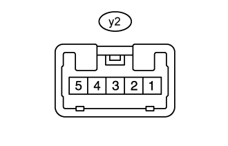
Disconnect the y2 door control relay LH connector.
-
Measure the resistance and voltage according to the value(s) in the table below.
Terminal No. (Symbol) Wiring Color Terminal Description Condition Specified Condition y2-1 (B) - Body ground B-R - Body ground Battery power supply Always 11 to 14 V y2-3 (E) - Body ground W-B - Body ground Ground Always Below 1 Ω -
Reconnect the y2 door control rely LH connector.
-
Measure the voltage according to the value(s) in the table below.
Terminal No. (Symbol) Wiring Color Terminal Description Condition Specified Condition y2-4 (SW) - Body ground L - Body ground*1, *4
SB - Body ground*2, *3, *5
Battery power supply Slide door LH open → halfway position Below 1 V → 11 to 14 V y2-5 (RLY) - Body ground G - Body ground Battery power supply Slide door LH open → halfway position (slide door closer operate) → approximately 18 seconds after the slide door LH halfway position or slide door LH open Below 1 V → 11 to 14 V → Below 1 V
-
*1: for 2TR-FE w/o Step Light
-
*2: for 1TR-FE
-
*3: for 2TR-FE w/ Step Light
-
*4: for 1KD-FTV w/o Entry and Start System
-
*5: for 1KD-FTV w/ Entry and Start System
-
-
-
CHECK DOOR CONTROL RELAY RH (w/o Power Slide Door)
-
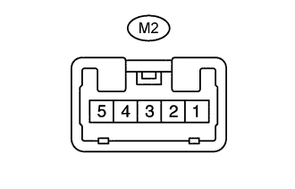
Disconnect the M2 door control relay RH connector.
-
Measure the resistance and voltage according to the value(s) in the table below.
Terminal No. (Symbol) Wiring Color Terminal Description Condition Specified Condition M2-1 (ECUB) - Body ground B-R - Body ground Battery power supply Always 11 to 14 V M2-3 (GND) - Body ground W-B - Body ground Ground Always Below 1 Ω -
Reconnect the M2 door control rely RH connector.
-
Measure the voltage according to the value(s) in the table below.
Terminal No. (Symbol) Wiring Color Terminal Description Condition Specified Condition M2-4 (FUL) - Body ground B - Body ground Battery power supply Slide door RH open → halfway position Below 1 V → 11 to 14 V M2-5 (IG) - Body ground G - Body ground Battery power supply Slide door RH open → halfway position (slide door closer operate) → approximately 18 seconds after the slide door RH halfway position or slide door RH open Below 1 V → 11 to 14 V → Below 1 V
-
-
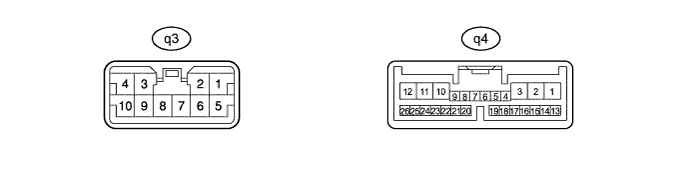
CHECK DOOR CONTROL RELAY ASSEMBLY (for LH Side [w/ Power Slide Door])
-
Disconnect the q3 and q4 door control relay assembly connectors.
-
Measure the resistance and voltage according to the value(s) in the table below.
Terminal No. (Symbol) Wiring Color Terminal Description Condition Specified Condition q3-7 (GND) - Body ground W-B - Body ground Ground Always Below 1 Ω q3-8 (B) - Body ground B-R - Body ground Battery power supply Always 11 to 14 V q4-9 (IG) - Body ground SB - Body ground Ignition power supply Ignition switch ON 11 to 14 V q4-9 (IG) - Body ground SB - Body ground Ignition power supply Ignition switch off Below 1 V q4-11 (ECUB) - Body ground W - Body ground Battery power supply Always 11 to 14 V q4-21 (SEL) - Body ground W-B - Body ground Ground Always Below 1 Ω q4-5 (FUL) - Body ground BE - Body ground Full latch switch input Slide door LH open → fully closed Below 1 Ω → 10 kΩ or higher q4-4 (HAF) - Body ground B - Body ground Half latch switch input Slide door LH fully open → half latched Below 1 Ω → 10 kΩ or higher q4-18 (POL) - Body ground R - Body ground Pawl switch input Slide door LH fully closed → half latched (latch pushed slightly toward full latch position) 10 kΩ or higher → Below 1 Ω → 10 kΩ or higher q4-18 (POL) - Body ground R - Body ground Pawl switch input Half latched Below 1 Ω q4-18 (POL) - Body ground R - Body ground Pawl switch input Slide door LH fully open → half latched (latch pushed slightly toward full latch position) 10 kΩ or higher → Below 1 Ω → 10 kΩ or higher -
Reconnect the q3 and q4 door control relay assembly connectors.
-
Measure the voltage according to the value(s) in the table below.
Terminal No. (Symbol) Wiring Color Terminal Description Condition Specified Condition Q3-1 (DC-) - Body ground P - Body ground Door closer output Slide door LH open → halfway position → normal rotation operation → revers rotation operation → operation stop Below 1 V → Below 1 V → Below 1 V → 11 to 14 V → Below 1 V Q3-5 (DC+) - Body ground L - Body ground Door closer output Slide door LH open → halfway position → normal rotation operation → revers rotation operation → operation stop Below 1 V → Below 1 V → 11 to 14 V → Below 1 V → Below 1 V Q4-19 (LMT) - Body ground W - Body ground Initial position switch input Slide door LH open → halfway position → normal rotation operation → pull the slide door outside handle or inside handle → revers rotation operation → operation stop 11 to 14 V → 11 to 14 V → Below 1 V → 11 to 14 V → Below 1 V → 11 to 14 V
-
-
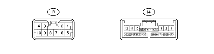
CHECK DOOR CONTROL RELAY ASSEMBLY (for RH Side [w/ Power Slide Door])
-
Disconnect the I3 and I4 door control relay assembly connectors.
-
Measure the resistance and voltage according to the value(s) in the table below.
Terminal No. (Symbol) Wiring Color Terminal Description Condition Specified Condition I3-7 (GND) - Body ground W-B - Body ground Ground Always Below 1 Ω I3-8 (B) - Body ground B-R - Body ground Battery power supply Always 11 to 14 V I4-9 (PCV1) - Body ground B - Body ground Ignition power supply Ignition switch ON 11 to 14 V I4-9 (PCV1) - Body ground B - Body ground Ignition power supply Ignition switch off Below 1 V I4-11 (ECUB) - Body ground W - Body ground Battery power supply Always 11 to 14 V I4-21 (SEL) - Body ground W-B - Body ground Ground Always Below 1 Ω I4-5 (FUL) - Body ground Y - Body ground Full latch switch input Slide door RH open → fully closed Below 1 Ω → 10 kΩ or higher I4-4 (HAF) - Body ground B - Body ground Half latch switch input Slide door RH fully open → half latched Below 1 Ω → 10 kΩ or higher I4-18 (POL) - Body ground R - Body ground Pawl switch input Slide door RH fully closed → half latched (latch pushed slightly toward full latch position) 10 kΩ or higher → Below 1 Ω → 10 kΩ or higher I4-18 (POL) - Body ground R - Body ground Pawl switch input Half latched Below 1 Ω I4-18 (POL) - Body ground R - Body ground Pawl switch input Slide door RH fully open → half latched (latch pushed slightly toward full latch position) 10 kΩ or higher → Below 1 Ω → 10 kΩ or higher -
Reconnect the I3 and I4 door control relay assembly connectors.
-
Measure the voltage according to the value(s) in the table below.
Terminal No. (Symbol) Wiring Color Terminal Description Condition Specified Condition I3-1 (DC-) - Body ground P - Body ground Door closer output Slide door RH open → halfway position → normal rotation operation → revers rotation operation → operation stop Below 1 V → Below 1 V → Below 1 V → 11 to 14 V → Below 1 V I3-5 (DC+) - Body ground L - Body ground Door closer output Slide door RH open → halfway position → normal rotation operation → revers rotation operation → operation stop Below 1 V → Below 1 V → 11 to 14 V → Below 1 V → Below 1 V I4-19 (LMT) - Body ground W - Body ground Initial position switch input Slide door RH open → halfway position → normal rotation operation → pull the slide door outside handle or inside handle → revers rotation operation → operation stop 11 to 14 V → 11 to 14 V → Below 1 V → 11 to 14 V → Below 1 V → 11 to 14 V
-