POWER SLIDE DOOR SYSTEM Power Slide Door RH does not Operate When Satellite Switch is Pressed
DESCRIPTION
The door control relay assembly controls the power slide door and activates the slide motor unit RH.
Tech Tips
Before using this flowchart, perform the self-diagnostic mode inspection Click here and make sure no code is output.
WIRING DIAGRAM
INSPECTION PROCEDURE
Note
Inspect the fuses for circuits related to this system before performing the following inspection procedure.
PROCEDURE
-
CHECK BASIC FUNCTIONS
-
When the engine is running, (1) to (5) are required for the power slide door to operate.
-
The battery voltage is 11 V or more.
-
The vehicle's speed is less than 3 km/h (1 mph) and the shift lever is moved to the P position.
-
The power slide door main switch is turned ON (the button is not pushed).
-
The slide door is unlocked (the position switch is ON).
-
An open circuit in the power slide door sensor assembly RH is not detected.
-
-
When the engine is not running, (1) to (4) are required for the power slide door to operate.
-
The battery voltage is 11 V or more.
-
The power slide door main switch is turned ON (the button is not pushed).
-
The slide door is unlocked (the position switch is ON).
-
An open circuit in the power slide door sensor assembly RH is not detected.
Tech Tips
-
For the inside handle, the power slide door can operate only when the child lock is OFF.
-
For the outside handle, the power slide door can operate even when the child lock is ON.
-
-
-
Check that the power slide door malfunctions.
Result Result Proceed to Nothing operates or moves A Motor is emitting sounds but slide door does not move (lock is released but door does not open) B
B 
INSPECT SLIDE DOOR MOTOR UNIT RH Click here
A 
-
-
CHECK HARNESS AND CONNECTOR (DOOR CONTROL RELAY ASSEMBLY - BATTERY AND BODY GROUND)
-
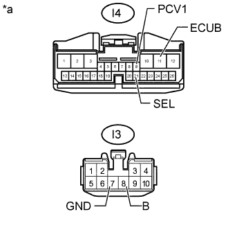
Text in Illustration *a Front view of wire harness connector
(to Door Control Relay Assembly)
Disconnect the door control relay assembly connectors.
-
Measure the resistance according to the value(s) in the table below.
Standard Resistance Tester Connection Condition Specified Condition I3-7 (GND) - Body ground Always Below 1 Ω I4-21 (SEL) - Body ground Always Below 1 Ω -
Measure the voltage according to the value(s) in the table below.
Standard Voltage Tester Connection Condition Specified Condition I3-8 (B) - Body ground Always 11 to 14 V I4-9 (PCV1) - Body ground Ignition switch ON 11 to 14 V I4-9 (PCV1) - Body ground Ignition switch off Below 1 V I4-11 (ECUB) - Body ground Always 11 to 14 V
NG 
REPAIR OR REPLACE HARNESS OR CONNECTOR
OK
-
-
INSPECT REAR DOOR WIRE RH
-
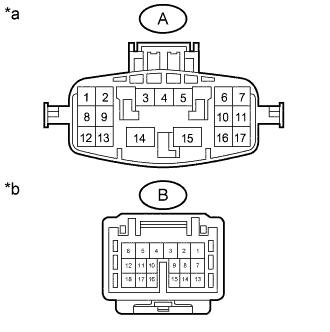
Text in Illustration *a Rear Door Wire RH
(Door Control Rely Assembly Side)
*b Rear Door Wire RH
(Door Opening Relay Side)
Disconnect the ci1 and fc1 rear door wire RH connectors.
-
Measure the resistance according to the value(s) in the table below.
Standard resistance Tester Connection Condition Specified Condition A-3 - B-6 Always Below 1 Ω A-1 - B-5 Always Below 1 Ω A-15 - B-1 Always Below 1 Ω
NG
REPLACE REAR DOOR WIRE RH Click here
OK
-
-
CHECK HARNESS AND CONNECTOR (DOOR OPENING RELAY - BATTERY AND BODY GROUND)
-
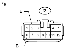
Text in Illustration *a Front view of wire harness connector
(to Door Opening Relay)
Disconnect the door opening relay connector.
-
Measure the resistance according to the value(s) in the table below.
Standard Resistance Tester Connection Condition Specified Condition f2-2 (E) - Body ground Always Below 1 Ω -
Measure the voltage according to the value(s) in the table below.
Standard Voltage Tester Connection Condition Specified Condition f2-6 (B) - Body ground Always 11 to 14 V
NG
REPAIR OR REPLACE HARNESS OR CONNECTOR
OK
-
-
INSPECT POWER SLIDE DOOR MAIN SWITCH
-
Remove the power slide door main switch Click here.
-
Inspect the power slide door main switch Click here.
NG
REPLACE POWER SLIDE DOOR MAIN SWITCH Click here
OK
-
-
CHECK HARNESS AND CONNECTOR (POWER SLIDE DOOR MAIN SWITCH - DOOR CONTROL RELAY ASSEMBLY)
-
Disconnect the I29 power slide door main switch connector.
-
Disconnect the I4 door control relay assembly connector.
-
Measure the resistance according to the value(s) in the table below.
Standard Resistance Tester Connection Condition Specified Condition I29-9 - I4-17 (MSW) Always Below 1 Ω I29-6 - Body ground Always Below 1 Ω I29-9 or I4-17 (MSW) - Body ground Always 10 kΩ or higher
NG
REPAIR OR REPLACE HARNESS OR CONNECTOR
OK
-
-
INSPECT AUTO SLIDE DOOR CONTROL SWITCH ASSEMBLY
-
Remove the auto slide door control switch assembly Click here.
-
Inspect the auto slide door control switch assembly Click here.
NG
REPLACE AUTO SLIDE DOOR CONTROL SWITCH ASSEMBLY Click here
OK
-
-
CHECK HARNESS AND CONNECTOR (AUTO SLIDE DOOR CONTROL SWITCH ASSEMBLY - DOOR CONTROL RELAY ASSEMBLY)
-
Disconnect the I31 auto slide door control switch assembly connector.
-
Disconnect the I4 door control relay assembly connector.
-
Measure the resistance according to the value(s) in the table below.
Standard Resistance Tester Connection Condition Specified Condition I31-8 - I4-16 (DSW) Always Below 1 Ω I31-5 - Body ground Always Below 1 Ω I31-8 or I4-16 (DSW) - Body ground Always 10 kΩ or higher
NG
REPAIR OR REPLACE HARNESS OR CONNECTOR
OK
-
-
CHECK HARNESS AND CONNECTOR (SLIDE DOOR MOTOR UNIT RH - DOOR CONTROL RELAY ASSEMBLY)
-
Disconnect the I1 slide door motor unit RH connector.
-
Disconnect the I4 door control relay assembly connector.
-
Measure the resistance according to the value(s) in the table below.
Standard Resistance Tester Connection Condition Specified Condition I1-1 (DSG) - I4-2 (DSG) Always Below 1 Ω I1-2 (DS2) - I4-24 (DS2) Always Below 1 Ω I1-3 (DSV) - I4-3 (DSV) Always Below 1 Ω I1-4 (DS1) - I4-23 (DS1) Always Below 1 Ω I1-1 (DSG) or I4-2 (DSG) - Body ground Always 10 kΩ or higher I1-2 (DS2) or I4-24 (DS2) - Body ground Always 10 kΩ or higher I1-3 (DSV) or I4-3 (DSV) - Body ground Always 10 kΩ or higher I1-4 (DS1) or I4-23 (DS1) - Body ground Always 10 kΩ or higher
NG
REPAIR OR REPLACE HARNESS OR CONNECTOR
OK
-
-
INSPECT SLIDE DOOR LOCK RELEASE MOTOR ASSEMBLY RH
-
Remove the slide door lock release motor assembly RH Click here.
-
Inspect the slide door lock release motor assembly RH Click here.
NG
REPLACE SLIDE DOOR LOCK RELEASE MOTOR ASSEMBLY RH Click here
OK
-
-
CHECK HARNESS AND CONNECTOR (SLIDE DOOR LOCK RELEASE MOTOR ASSEMBLY RH - DOOR OPENING RELAY)
-
Disconnect the f3 slide door lock release motor assembly connector.
-
Disconnect the f2 door opening relay connector.
-
Measure the resistance according to the value(s) in the table below.
Standard Resistance Tester Connection Condition Specified Condition f3-1 (GR) - f2-10 (MSE) Always Below 1 Ω f3-2 (LS2) - f2-12 (POS) Always Below 1 Ω f3-3 (L-) - f2-10 (MSE) Always Below 1 Ω f3-4 (ANRL) - f2-5 (HSW) Always Below 1 Ω f3-5 (SD-) - f2-1 (DC-) Always Below 1 Ω f3-6 (SD+) - f2-3 (DC+) Always Below 1 Ω f3-1 (GR) or f2-10 (MSE) - Body ground Always 10 kΩ or higher f3-2 (LS2) or f2-12 (POS) - Body ground Always 10 kΩ or higher f3-3 (L-) or f2-10 (MSE) - Body ground Always 10 kΩ or higher f3-4 (ANRL) or f2-5 (HSW) - Body ground Always 10 kΩ or higher f3-5 (SD-) or f2-1 (DC-) - Body ground Always 10 kΩ or higher f3-6 (SD+) or f2-3 (DC-) - Body ground Always 10 kΩ or higher
NG
REPAIR OR REPLACE HARNESS OR CONNECTOR
OK
-
-
CHECK HARNESS AND CONNECTOR (DOOR CONTROL RELAY ASSEMBLY - DOOR OPENING RELAY)
-
Disconnect the I4 door control relay assembly connector.
-
Disconnect the f2 door opening relay connector.
-
Measure the resistance according to the value(s) in the table below.
Standard Resistance Tester Connection Condition Specified Condition I4-12 (RACT) - f2-4 (MPX1) Always Below 1 Ω I4-12 (RACT) - f2-11 (MPX2) Always Below 1 Ω I4-12 (RACT) or f2-4 (MPX1) - Body ground Always 10 kΩ or higher I4-12 (RACT) or f2-11 (MPX2) - Body ground Always 10 kΩ or higher
NG
REPAIR OR REPLACE HARNESS OR CONNECTOR
OK
-
-
REPLACE DOOR OPENING RELAY
-
Temporarily replace the door opening relay with a new or normally functioning one Click here.
NEXT
-
-
CHECK OPERATION
-
Check the operation of the power slide door function Click here.
OK Power slide door function operates normally.
NG
REPLACE DOOR CONTROL RELAY ASSEMBLY Click here
OK 
END (DOOR OPENING RELAY WAS DEFECTIVE)
-
-
INSPECT SLIDE DOOR MOTOR UNIT RH
-
Remove the slide door motor unit RH Click here.
-
Inspect the slide door motor unit RH Click here.
NG
REPLACE SLIDE DOOR MOTOR UNIT RH Click here
OK
-
-
CHECK HARNESS AND CONNECTOR (DOOR CONTROL RELAY ASSEMBLY - SLIDE DOOR MOTOR UNIT RH)
-
Disconnect the I3 and I4 door control relay assembly connectors.
-
Disconnect the I1 and I5 slide door motor unit RH connectors.
-
Measure the resistance according to the value(s) in the table below.
Standard Resistance Tester Connection Condition Specified Condition I3-2 (CL+) - I5-5 (CL+) Always Below 1 Ω I3-6 (CL-) - I5-4 (CL-) Always Below 1 Ω I4-2 (DSG) - I1-1 (DSG) Always Below 1 Ω I4-3 (DSV) - I1-3 (DSV) Always Below 1 Ω I4-24 (DS2) - I1-3 (DS2) Always Below 1 Ω I4-23 (DS1) - I1-4 (DS1) Always Below 1 Ω I3-2 (CL+) or I5-5 (CL+) - Body ground Always 10 kΩ or higher I3-6 (CL-) or I5-4 (CL-) - Body ground Always 10 kΩ or higher I4-2 (DSG) or I1-1 (DSG) - Body ground Always 10 kΩ or higher I4-3 (DSV) or I1-3 (DSV) - Body ground Always 10 kΩ or higher I4-24 (DS2) or I1-3 (DS2) - Body ground Always 10 kΩ or higher I4-23 (DS1) or I1-4 (DS1) - Body ground Always 10 kΩ or higher
NG
REPAIR OR REPLACE HARNESS OR CONNECTOR
OK
REPLACE DOOR CONTROL RELAY ASSEMBLY Click here
-