POWER SLIDE DOOR SYSTEM, Diagnostic DTC:1-2
| DTC Code | DTC Name |
|---|---|
| 1-2 | Power Slide Door Sensor Malfunction |
DESCRIPTION
When the door control relay assembly receives a jam signal from the power slide door sensor assembly or power slide door assembly RH*, the door control relay assembly stops closing the power slide door.
When the door control relay assembly determines the open circuit in the power slide door sensor assembly or power slide door sensor assembly RH* circuit, code 1-2 is output.
| DTC No. | DTC Detection Condition | Trouble Area |
|---|---|---|
| 1-2 |
|
|
-
*: for RH Side, w/ Power Slide Door
WIRING DIAGRAM
INSPECTION PROCEDURE
PROCEDURE
-
CLEAR DTC
-
Clear the DTC Click here.
NEXT 
-
-
CHECK FOR DTC
-
Check for DTC Click here.
Result Result Proceed to DTC is not output A DTC is output (for LH Side) B DTC is output (for RH Side, w/ Power Slide Door) C
B 
INSPECT POWER SLIDE DOOR SENSOR ASSEMBLY Click here
C
INSPECT POWER SLIDE DOOR SENSOR ASSEMBLY RH Click here
A 
USE SIMULATION METHOD TO CHECK Click here
-
-
INSPECT POWER SLIDE DOOR SENSOR ASSEMBLY
-
Remove the power slide door sensor assembly Click here.
-
Inspect the power slide door sensor assembly Click here.
NG 
REPLACE POWER SLIDE DOOR SENSOR ASSEMBLY Click here
OK
-
-
INSPECT NO. 2 REAR DOOR WIRE
-
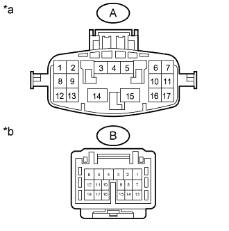
Text in Illustration *a No. 2 Rear Door Wire
(Door Control Relay Assembly Side)
*b No. 2 Rear Door Wire
(Power Slide Door Sensor Assembly Side)
Disconnect the oq1 and po2 No. 2 rear door wire connectors.
-
Measure the resistance according to the value(s) in the table below.
Standard Resistance Tester Connection Condition Specified Condition A-13 - B-10 Always Below 1 Ω A-10 - B-16 Always Below 1 Ω
NG
REPLACE NO. 2 REAR DOOR WIRE Click here
OK
-
-
CHECK HARNESS AND CONNECTOR (POWER SLIDE DOOR SENSOR ASSEMBLY - DOOR CONTROL RELAY ASSEMBLY)
-
Disconnect the p6 power slide door sensor assembly connector.
-
Disconnect the q4 door control relay assembly connector.
-
Measure the resistance according to the value(s) in the table below.
Standard Resistance Tester Connection Condition Specified Condition p6-1 - q4-14 (OS) Always Below 1 Ω p6-2 - q4-13 (OSG) Always Below 1 Ω p6-1 or q4-14 (OS) - Body ground Always 10 kΩ or higher p6-2 or q4-13 (OSG) - Body ground Always 10 kΩ or higher
NG
REPAIR OR REPLACE HARNESS OR CONNECTOR
OK
REPLACE DOOR CONTROL RELAY ASSEMBLY Click here
-
-
INSPECT POWER SLIDE DOOR SENSOR ASSEMBLY RH
-
Remove the power slide door sensor assembly RH Click here.
-
Inspect the power slide door sensor assembly RH Click here.
NG
REPLACE POWER SLIDE DOOR SENSOR ASSEMBLY RH Click here
OK
-
-
INSPECT REAR DOOR WIRE RH
-
Text in Illustration *a Rear Door Wire RH
(Door Control Relay Assembly Side)
*b Rear Door Wire RH
(Power Slide Door Sensor Assembly RH Side)
Disconnect the ci1 and fc1 rear door wire RH connectors.
-
Measure the resistance according to the value(s) in the table below.
Standard Resistance Tester Connection Condition Specified Condition A-13 - B-10 Always Below 1 Ω A-10 - B-16 Always Below 1 Ω
NG
REPLACE REAR DOOR WIRE RH Click here
OK
-
-
CHECK HARNESS AND CONNECTOR (POWER SLIDE DOOR SENSOR ASSEMBLY RH - DOOR CONTROL RELAY ASSEMBLY)
-
Disconnect the f6 power slide door sensor assembly RH connector.
-
Disconnect the I4 door control relay assembly connector.
-
Measure the resistance according to the value(s) in the table below.
Standard Resistance Tester Connection Condition Specified Condition f6-1 - I4-14 (OS) Always Below 1 Ω f6-2 - I4-13 (OSG) Always Below 1 Ω f6-1 or I4-14 (OS) - Body ground Always 10 kΩ or higher f6-2 or I4-13 (OSG) - Body ground Always 10 kΩ or higher
NG
REPAIR OR REPLACE HARNESS OR CONNECTOR
OK
REPLACE DOOR CONTROL RELAY ASSEMBLY Click here
-