POWER SLIDE DOOR SYSTEM Park / Neutral Position Switch Circuit
DESCRIPTION
The park/neutral position switch assembly outputs switch signals to the door control relay assembly.
WIRING DIAGRAM
INSPECTION PROCEDURE
Note
Inspect the fuses for circuits related to this system before performing the following inspection procedure.
PROCEDURE
-
CHECK DOOR CONTROL RELAY ASSEMBLY
-
for LH Side
-

Text in Illustration *a Front view of wire harness connector
(to Door Control Relay Assembly)
Disconnect the door control relay assembly connector.
-
Measure the voltage according to the value(s) in the table below.
Standard Voltage Tester Connection Condition Specified Condition q4-10 (CPSW) - Body ground Ignition switch ON, shift lever not in P Below 1 V q4-10 (CPSW) - Body ground Ignition switch ON, shift lever in P 11 to 14 V
-
-
for RH Side, w/ Power Slide Door
-
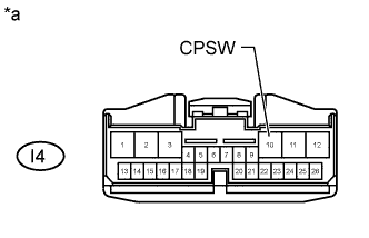
Text in Illustration *a Front view of wire harness connector
(to Door Control Relay Assembly)
Disconnect the door control relay assembly connector.
-
Measure the voltage according to the value(s) in the table below.
Standard Voltage Tester Connection Condition Specified Condition I4-10 (CPSW) - Body ground Ignition switch ON, shift lever not in P Below 1 V I4-10 (CPSW) - Body ground Ignition switch ON, shift lever in P 11 to 14 V
-
NG 
INSPECT PARK/NEUTRAL POSITION SWITCH ASSEMBLY Click here
OK 
PROCEED TO NEXT SUSPECTED AREA SHOWN IN PROBLEM SYMPTOMS TABLE Click here
-
-
INSPECT PARK/NEUTRAL POSITION SWITCH ASSEMBLY
-
Remove the park/neutral position switch assembly.
-
for A340E : Click here
-
for A343E : Click here
-
for AC60E : Click here
-
-
Inspect the park/neutral position switch assembly.
-
for A340E : Click here
-
for A343E : Click here
-
for AC60E : Click here
Result Result Proceed to OK A NG (for A340E) B NG (for A343E) C NG (for AC60E) D -
B 
REPLACE PARK/NEUTRAL POSITION SWITCH ASSEMBLY Click here
C
REPLACE PARK/NEUTRAL POSITION SWITCH ASSEMBLY Click here
D
REPLACE PARK/NEUTRAL POSITION SWITCH ASSEMBLY Click here
A
REPAIR OR REPLACE HARNESS OR CONNECTOR
-