FUEL TANK REMOVAL

-
DISCHARGE FUEL SYSTEM PRESSURE
-
Check that the battery positive voltage is above 12 V.
-
Discharge the fuel system pressure Click here.
-
Disconnect the negative terminal cable from the battery.
-
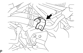
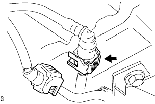
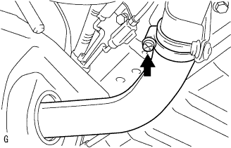
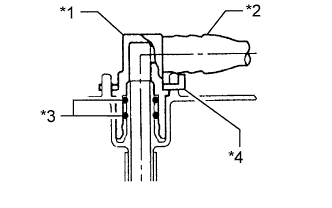
Pinch and pull the No. 1 fuel hose (fuel tube connector) to disconnect it from the fuel pressure pulsation damper assembly.
CAUTION:
-
Always read the precautions Click here before disconnecting the fuel tube connector (quick type).
-
The fuel tube may spray fuel as a result of pressure that remains in it. Do not allow fuel to be sprayed in the engine compartment.
-
-
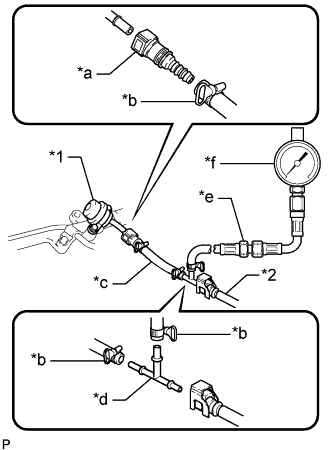
Text in Illustration *1 Fuel Pressure Pulsation Damper Assembly *2 No. 1 Fuel Hose *a SST (Fuel Tube Connector) *b SST (Hose Band) *c SST (Hose) *d SST (T-Joint) *e SST (Hose Joint) *f SST (Pressure Gauge) Install SST (pressure gauge) as shown in the illustration.
- SST
- 09268-45101 ( 09268-41250, 09268-41260, 09268-41280, 09268-41500, 09268-41700, 95336-08070 )
-
Wipe off any gasoline.
-
Reconnect the negative terminal cable.
-
Operate the fuel pump.
-
Connect the intelligent tester to the DLC3.
-
Turn the ignition switch to ON.
Note
Do not start the engine.
-
Turn the intelligent tester on.
-
Enter the following menus: Powertrain / Engine and ECT / Active Test / Control the Fuel Pump / Speed.
-
-
Measure the fuel pressure.
Standard fuel pressure 281 to 287 kPa (2.87 to 2.93 kgf/cm2, 40.8 to 41.7 psi) If the pressure is higher than the specification, replace the fuel pressure regulator assembly.
If the pressure is lower than the specification, check the fuel hoses and connections, fuel pump, fuel filter assembly and fuel pressure regulator assembly.
-
Start the engine.
-
Measure the fuel pressure.
Standard fuel pressure 281 to 287 kPa (2.87 to 2.93 kgf/cm2, 40.8 to 41.7 psi) If the pressure is not as specified, check the fuel pump, fuel pressure regulator assembly and/or fuel injector assemblies.
-
Stop the engine.
-
Check that the fuel pressure remains as specified for 5 minutes after the engine has stopped.
Standard fuel pressure 147 kPa (1.5 kgf/cm2, 21 psi) or more If the pressure is not as specified, check the fuel pump, fuel pressure regulator assembly and/or fuel injector assemblies.
-
After checking the fuel pressure, disconnect the negative terminal cable and carefully remove SST and the fuel tube connector to prevent gasoline from spraying.
-
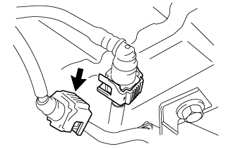
Reconnect the No. 1 fuel hose (fuel tube connector) to the fuel pressure pulsation damper assembly.
-
-
REMOVE PROPELLER SHAFT ASSEMBLY
Tech Tips
-
Propeller shaft assembly for Super Long Wheelbase Click here.
-
Propeller shaft assembly for Long Wheelbase Click here.
-
-
DISCONNECT FUEL TANK WIRE
-
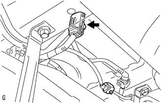
Disconnect the fuel tank wire connector.
-
-
DISCONNECT NO. 1 FUEL EVAPORATION TUBE SUB-ASSEMBLY
-
Disconnect the No. 1 fuel evaporation tube sub-assembly Click here.
-
-
DISCONNECT FUEL TANK RETURN TUBE
-
Disconnect the fuel tank return tube Click here.
-
-
DISCONNECT FUEL TANK MAIN TUBE SUB-ASSEMBLY
-
Disconnect the fuel tank main tube sub-assembly Click here.
-
-
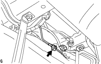
DISCONNECT FUEL TANK BREATHER HOSE
-
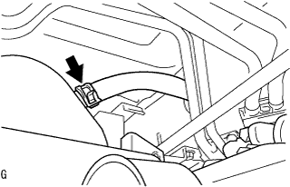
Slide the clamp and disconnect the fuel tank breather hose from the fuel tank assembly.
-
-
REMOVE FUEL HOSE PROTECTOR
-
Detach the 2 claws to remove the fuel hose protector from the fuel tank to filler pipe hose.
-
-
DISCONNECT FUEL TANK TO FILLER PIPE HOSE
-
Loosen the hose clamp to disconnect the fuel tank to filler pipe hose from the fuel tank inlet pipe sub-assembly.
-
-
REMOVE FUEL TANK ASSEMBLY
-
Remove the bolt and disconnect the No. 3 parking brake cable assembly.
-
Hold the fuel tank assembly using an engine lifter.
-
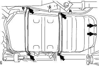
Remove the 6 bolts, No. 1 fuel tank band sub-assembly RH and No. 1 fuel tank band sub-assembly LH.
-
Operate the engine lifter, and then remove the fuel tank assembly.
-
-
DISCONNECT NO. 1 FUEL EVAPORATION TUBE SUB-ASSEMBLY
-
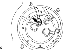
Disconnect the No. 1 fuel evaporation tube sub-assembly from the fuel suction with pump and gauge tube assembly Click here.
-
-
DISCONNECT FUEL TANK RETURN TUBE
-
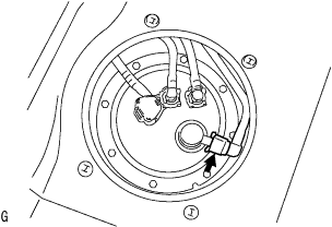
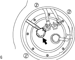
Text in Illustration *1 Fuel Tube Joint *2 Fuel Tube *3 O-Ring *4 Tube Joint Clip Remove the tube joint clip and pull the fuel tank return tube out of the plug of the fuel suction with pump and gauge tube assembly.
Note
-
Remove any dirt and foreign matter on the fuel tube joint before performing this step.
-
Do not allow any scratches or foreign matter on the parts when disconnecting them as the fuel tube joint contains the O-rings that seal the plug.
-
Perform this step by hand. Do not use any tools.
-
Do not forcibly bend or twist the nylon tube.
-
Protect the disconnected parts by covering them with plastic bags and tape after disconnecting the fuel tubes.
-
-
-
DISCONNECT FUEL TANK MAIN TUBE SUB-ASSEMBLY
-
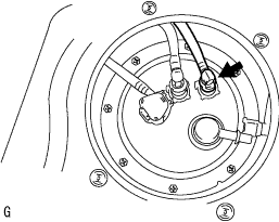
Text in Illustration *1 Fuel Tube Joint *2 Fuel Tube *3 O-Ring *4 Tube Joint Clip Remove the tube joint clip and pull the fuel tank main tube sub-assembly out of the plug of the fuel suction with pump and gauge tube assembly.
Note
-
Remove any dirt and foreign matter on the fuel tube joint before performing this step.
-
Do not allow any scratches or foreign matter on the parts when disconnecting them as the fuel tube joint contains the O-rings that seal the plug.
-
Perform this step by hand. Do not use any tools.
-
Do not forcibly bend or twist the nylon tube.
-
Protect the disconnected parts by covering them with plastic bags and tape after disconnecting the fuel tubes.
-
-
-
DISCONNECT FUEL SUCTION WITH PUMP AND GAUGE TUBE ASSEMBLY
-
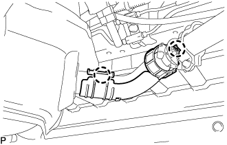
Disconnect the fuel tank wire connector.
-
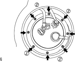
Press down on the fuel suction with pump and gauge tube assembly and remove the 8 bolts and fuel tank vent tube set plate.
Note
-
When the fuel tank vent tube set plate is removed, be careful as the fuel suction with pump and gauge tube assembly will spring upward from the force of the spring.
-
Remove any foreign matter around the fuel suction with pump and gauge tube assembly before this operation.
-
-
Remove the fuel suction with pump and gauge tube assembly from the fuel tank assembly.
Note
Be careful not to bend the arm of the fuel sender gauge assembly.
-
Remove the fuel suction tube set gasket from the fuel tank assembly.
-
-
REMOVE FUEL HOSE GROMMET
-
Remove the fuel hose grommet from the fuel tank assembly.
-