FUEL PUMP INSTALLATION
-
INSTALL FUEL SUCTION WITH PUMP AND GAUGE TUBE ASSEMBLY
-
Apply a light coat of gasoline or grease to a new fuel suction tube set gasket and install the fuel suction tube set gasket to the fuel tank assembly.
-
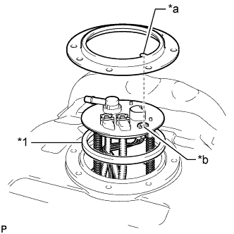
Text in Illustration *1 Fuel Suction Tube Set Gasket *a Protrusion *b Groove Align the protrusion of the fuel tank vent tube set plate with the groove of the fuel suction with pump and gauge tube assembly.
Note
Be careful not to bend the arm of the fuel sender gauge assembly.
-
Install the fuel tank vent tube set plate with the 8 bolts.
- Torque:
- 6.0 N*m { 61 kgf*cm, 53 in.*lbf }
-
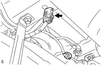
Connect the fuel tank wire connector.
-
-
CONNECT FUEL TANK MAIN TUBE SUB-ASSEMBLY
-
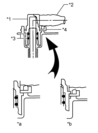
Push the fuel tank main tube sub-assembly into the plug of the fuel suction with pump and gauge tube assembly, and then install the tube joint clip.
Note
-
Check that there are no scratches or foreign matter on the connecting parts.
-
Check that the fuel tube joints are inserted securely.
-
Check that the tube joint clips are on the collars of the fuel tube joints.
-
After installing the tube joint clips, check that the fuel tube joints cannot be pulled off.
Text in Illustration *1 Fuel Tube Joint *2 Fuel Tube *3 O-Ring *4 Tube Joint Clip *a CORRECT *b INCORRECT -
-
-
CONNECT FUEL TANK RETURN TUBE
-
Push the fuel tank return tube into the plug of the fuel suction with pump and gauge tube assembly, and then install the tube joint clip.
Note
-
Check that there are no scratches or foreign matter on the connecting parts.
-
Check that the fuel tube joints are inserted securely.
-
Check that the tube joint clips are on the collars of the fuel tube joints.
-
After installing the tube joint clips, check that the fuel tube joints cannot be pulled off.
Text in Illustration *1 Fuel Tube Joint *2 Fuel Tube *3 O-Ring *4 Tube Joint Clip *a CORRECT *b INCORRECT -
-
-
CONNECT NO. 1 FUEL TANK EVAPORATION TUBE SUB-ASSEMBLY
-
Connect the No. 1 fuel evaporation tube sub-assembly to the fuel suction with pump and gauge tube sub-assembly Click here.
-
-
INSTALL FUEL TANK INSPECTION HOLE COVER
-
Install the fuel tank inspection hole cover with the 4 screws.
-
-
CONNECT BATTERY NEGATIVE CABLE
-
CHECK FOR FUEL LEAKS
-
When using the intelligent tester
-
Connect the intelligent tester to the DLC3.
-
Turn the ignition switch to the on position and intelligent tester main switch ON.
Note
Do not start the engine.
-
Select the Active Test mode on the intelligent tester.
Tech Tips
Please refer to the intelligent tester operator's manual for further details.
-
-
When not using the intelligent tester.
-
Disconnect the fuel pump connector.
-
Using a service wire, connect terminals FP and +B of the relay block.
Note
Pay attention to the terminal connecting position to avoid a malfunction.
-
Turn the ignition switch to the ON position, and check that the fuel pump operates.
Note
Do not start the engine.
-
-
Check that there are no fuel leaks anywhere on the fuel system after doing maintenance.
-
Check that the pulsation damper screw rises up when the fuel pump operates.
If operation is not as specified, check the following parts:
-
Fusible link
-
Fuel pump
-
Wiring connections
-
ECM
-
Fuses
-
-
Turn the ignition switch off.
-
Disconnect the intelligent tester from the DLC3.
-