EGR VALVE (w/o DPF) INSTALLATION
-
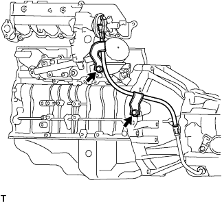
INSTALL NO. 2 EGR PIPE SUB-ASSEMBLY
-
Install a new gasket and the No. 2 EGR pipe with the 2 nuts.
- Torque:
- 13 N*m { 133 kgf*cm, 10 ft.*lbf }
-
-
INSTALL ELECTRIC EGR CONTROL VALVE ASSEMBLY
-
Install the vacuum regulating valve with the 2 bolts.
- Torque:
- 20 N*m { 204 kgf*cm, 15 ft.*lbf }
-
Install a new gasket and the electric EGR valve to the intake air connector.
-
Install 2 new gaskets and the electric EGR valve together with the intake air connector to the intake manifold with the bolt and 2 nuts.
- Torque:
- 20 N*m { 204 kgf*cm, 15 ft.*lbf }
-
Connect the 2 vacuum hoses to the vacuum regulating valve.
-
Connect the vacuum regulating valve connector.
-
-
INSTALL MANIFOLD STAY
-
Install the manifold stay with the 2 bolts.
- Torque:
- 19 N*m { 194 kgf*cm, 14 ft.*lbf }
-
-
INSTALL INTAKE AIR TEMPERATURE SENSOR
-
Install a new gasket to the intake air temperature sensor.
-
Using a 22 mm ball joint lock nut wrench, install the intake air temperature sensor.
- Torque:
- 34 N*m { 350 kgf*cm, 25 ft.*lbf }
Note
Use the formula to calculate special torque values for situations where a ball joint lock nut wrench is combined with a torque wrench Click here.
-
Connect the intake air temperature sensor connector.
-
-
INSTALL MANIFOLD ABSOLUTE PRESSURE SENSOR
-
Install the manifold absolute pressure sensor with the 2 bolts and connect the vacuum hose.
- Torque:
- 8.0 N*m { 82 kgf*cm, 71 in.*lbf }
-
-
INSTALL VACUUM SWITCHING VALVE ASSEMBLY
-
Install the vacuum switching valve with the bolt.
- Torque:
- 20 N*m { 204 kgf*cm, 15 ft.*lbf }
-
Connect the connector and vacuum hose to the vacuum switching valve.
-
Attach the clamp and wire harness.
-
Connect the connector to the electric EGR control valve.
-
-
CONNECT NO. 1 GAS FILTER
-
Connect the vacuum hose together with the gas filter.
-
Install the bolt.
- Torque:
- 8.0 N*m { 82 kgf*cm, 71 in.*lbf }
-
-
INSTALL ENGINE OIL LEVEL DIPSTICK GUIDE
-
Install a new O-ring to the engine oil level dipstick guide.
-
Apply a small amount of clean engine oil to the O-ring.
-
Install the engine oil level dipstick guide with the bolt.
- Torque:
- 8.0 N*m { 82 kgf*cm, 72 in.*lbf }
-
-
INSTALL TRANSMISSION OIL FILLER TUBE SUB-ASSEMBLY (for Automatic Transmission)
-
Coat a new O-ring with ATF and install it onto the oil filler tube sub-assembly.
-
Install the oil filler tube sub-assembly with the 2 bolts.
- Torque:
- 12 N*m { 122 kgf*cm, 9 ft.*lbf }
-
-
INSTALL DIESEL THROTTLE BODY ASSEMBLY
-
INSPECT FOR EXHAUST GAS LEAK
If gas is leaking, tighten the areas necessary to stop the leak. Replace damaged parts as necessary.
-
INSTALL NO. 2 ENGINE SERVICE HOLE COVER (for Standard Body)
-
Install the No. 2 engine service hole cover with the 3 bolts.
- Torque:
- 9.0 N*m { 92 kgf*cm, 80 in.*lbf }
-
Return the carpet to its original position and attach the clips.
-
-
INSTALL NO. 2 ENGINE UNDER COVER (for Cold Area Specification Vehicles)
-
Install the No. 2 engine under cover with the 6 bolts.
- Torque:
- 13 N*m { 133 kgf*cm, 10 ft.*lbf }
-
-
INSTALL NO. 1 ENGINE UNDER COVER (for Cold Area Specification Vehicles)
-
Install the No. 1 engine under cover with the 4 bolts.
- Torque:
- 13 N*m { 133 kgf*cm, 10 ft.*lbf }
-