FUEL TEMPERATURE SENSOR INSTALLATION

-
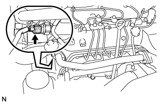
INSTALL FUEL TEMPERATURE SENSOR
-
Apply a light coat of light oil to a new O-ring.
-
Install the O-ring to the fuel temperature sensor.
-
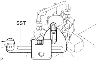
Using the SST, install the fuel temperature sensor.
- SST
- 09922-10010
- Torque:
- 22 N*m { 220 kgf*cm, 16 ft.*lbf }
-
-
INSTALL INJECTION OR SUPPLY PUMP ASSEMBLY
-
Confirm that the supply pump gear in the timing gear case moves back and forth smoothly.
-
Install a new O-ring and the pulley key to the supply pump.
-
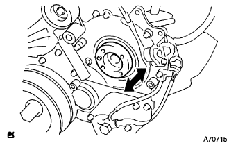
Aligning the projecting edge of the supply pump head to the key-slot of the supply pump gear, install the pump to the timing gear case.
-
While holding the supply pump by hand, push the supply pump gear rearward to engage the pump gear and drive shaft.
-
Temporarily install the supply pump with the 2 nuts.
-
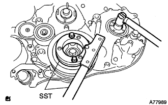
Using SST, hold the crankshaft.
- SST
- 09213-58013
- 09330-00021
-
Install the supply pump gear set nut.
Tech Tips
Set a new O-ring before tightening the supply pump gear set nut.
- Torque:
- 64 N*m { 653 kgf*cm, 47 ft.*lbf }
-
Temporarily install the supply pump stay with the 2 bolts on the engine block side.
-
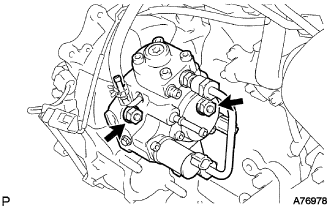
Tighten the 2 nuts for the injection pump.
- Torque:
- 21 N*m { 214 kgf*cm, 16 ft.*lbf }
-
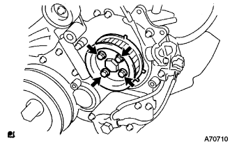
Install the camshaft timing pulley flange No.2 and pump drive shaft pulley with the 4 bolts.
- Torque:
- 31 N*m { 316 kgf*cm, 23 ft.*lbf }
-
-
CHECK PUMP DRIVE SHAFT THRUST CLEARANCE
-
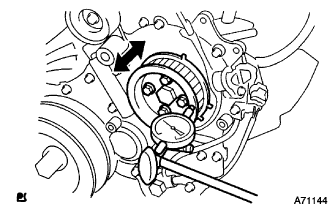
Push the pump drive shaft pulley back and forth to check a thrust clearance of the injection pump drive shaft.
Thrust clearance 0.15 to 0.55 mm (0.0059 to 0.0217 in.) Note
Make sure that the crankshaft pulley's notch is at 30 degree in the counterclockwise direction form the TDC position.
Tech Tips
If there is not thrust clearance, disassemble and reassemble the injection pump and pump drive shaft pulley.
-
-
INSTALL FUEL INLET PIPE SUB-ASSEMBLY
Note
-
When replacing the fuel supply pump, common rail, cylinder block, cylinder head, cylinder head gasket, or timing gear case with a new one, replace the fuel inlet pipe.
-
Be careful not to adhere dusts, dirt or any other materials onto the joint area of the fuel inlet pipe.
-
Temporarily install the fuel inlet pipe.
-
Using SST, tighten the injection pipe on the common rail side.
- SST
- 09023-12701
- Torque:
- 32 N*m { 326 kgf*cm, 24 ft.*lbf, for use with SST }
-
Using SST, tighten the injection pipe on the supply pump side.
- SST
- 09023-12701
- Torque:
- 32 N*m { 326 kgf*cm, 24 ft.*lbf, for use with SST }
-
-
INSTALL INJECTION PIPE
- SST
- 09023-12701
Note
-
When replacing the fuel injector, common rail, or cylinder head with a new one, replace injection pipes No. 1, No. 2, No. 3, and No. 4.
-
Keep clean the joint of the injection pipe.
-
Install the injection pipes.
-
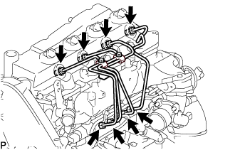
Temporarily install the 4 injection pipes.
-
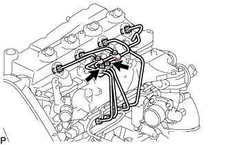
Install the injection pipe clamp No.3 in 2 nuts.
- Torque:
- 5.0 N*m { 51 kgf*cm, 44 in.*lbf }
-
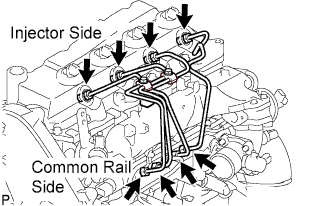
Fasten the union sequentially, from the injection pipe common rail to the injector, using SST.
- SST
- 09023-12701
- Torque:
- Use union nut wrench and torque wrench
- 32 N*m { 326 kgf*cm, 24 ft.*lbf }
-
-
INSTALL OIL LEVEL GAGE GUIDE
-
Install a new O-ring to the oil level gauge guide.
-
Apply a light coat of engine oil to the O-ring.
-
Install the oil level gauge guide with the bolt.
- Torque:
- 8.0 N*m { 82 kgf*cm, 71 in.*lbf }
-
Install the oil level gauge.
-
-
CONNECT INTAKE AIR CONNECTOR (w/o EGR Valve)
-
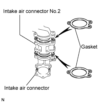
Temporarily install 2 new gaskets and intake air connector No.2 to the intake air connector.
-
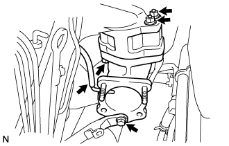
Temporarily tighten the intake air connector assembly with the bolt and 2 nuts.
-
Tighten the manifold stay with the bolt.
-
Tighten the intake air connector with the bolt and 2 nuts.
-
Install the vacuum hose to the intake air connector.
-
-
TEMPORARILY TIGHTEN ELECTRIC EGR CONTROL VALVE ASSEMBLY (w/ EGR Valve)
-
Temporarily tighten the EGR valve assembly with the sensor.
-
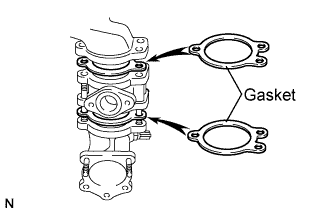
Install 2 new gaskets and the EGR valve to the intake air connector as shown in the illustration.
-
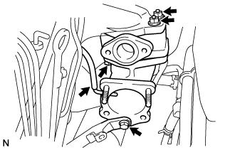
Temporarily tighten the intake air connector with EGR valve assembly to the intake manifold with the bolt and the 2 nuts.
-
Install the vacuum hose to the intake air connector.
-
Temporarily tighten the manifold stay with the bolt.
-
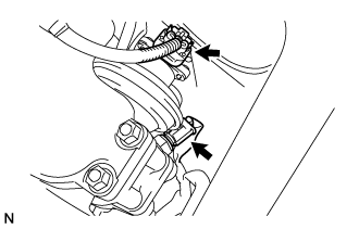
Connect the EGR valve position sensor connector.
-
Connect the intake air temperature sensor connector.
-
-
Install the vacuum regulating valve.
-
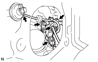
Install the vacuum regulating valve with the 2 bolts.
- Torque:
- 20 N*m { 204 kgf*cm, 15 ft.*lbf }
-
Connect the 2 vacuum hoses and the regulating valve connector.
-
-
-
INSTALL EGR PIPE SUB-ASSEMBLY NO.1 (w/ EGR Valve)
-
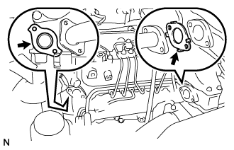
Install the 2 gaskets to the cylinder head and EGR pipe sub-assembly as shown in the illustration.
-
Install the EGR pipe sub-assembly with the 2 bolts and 2 nuts.
- Torque:
- 13 N*m { 133 kgf*cm, 10 ft.*lbf }
-
Tighten the intake air connector with the bolt and the 2 nuts.
- Torque:
- 20 N*m { 204 kgf*cm, 15 ft.*lbf }
-
Tighten the manifold stay.
- Torque:
- 19 N*m { 194 kgf*cm, 14 ft.*lbf }
-
-
REMOVE EGR PIPE SUB-ASSEMBLY NO.1 (w/ EGR Valve)
-
Remove the 3 bolts, the 2 nuts, and the EGR pipe sub-assembly.
-
Remove the 2 gaskets.
-
-
INSTALL DIESEL THROTTLE BODY ASSEMBLY
Note
After removing and installing, or replacing the throttle body, be sure to perform the operation check.
-
Install a new gasket to intake air connector.
-
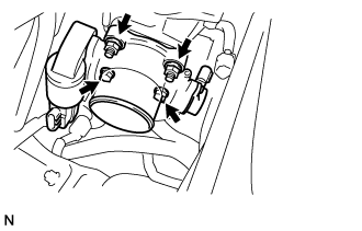
Install the throttle body with the 2 bolts and the 2 nuts.
- Torque:
- 20 N*m { 204 kgf*cm, 15 ft.*lbf }
-
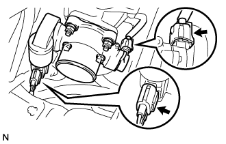
Connect the 2 throttle body connectors.
-
-
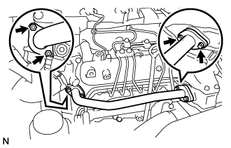
INSTALL AIR HOSE NO.4
-
Install the air hose No.4 with the 2 clamps.
- Torque:
- 6.0 N*m { 61 kgf*cm, 53 in.*lbf }
-
-
INSTALL EGR PIPE SUB-ASSEMBLY (w/ EGR Valve)
-
Install 2 new gaskets to the cylinder head and the EGR pipe sub-assembly No.1 as shown in the illustration.
-
Install the EGR pipe with the 2 bolts and the 2 nuts.
- Torque:
- 13 N*m { 133 kgf*cm, 10 ft.*lbf }
-
Connect the fuel pressure sensor connector.
-
-
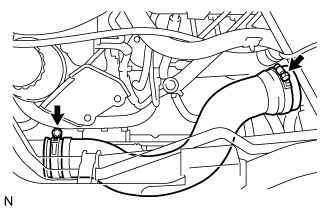
INSTALL OIL RETURN HOSE
-
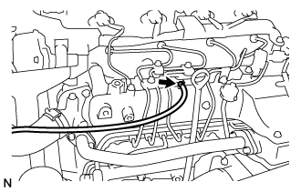
Connect the oil return hose with the clip.
-
-
INSTALL VANE PUMP OIL RESERVOIR ASSEMBLY
-
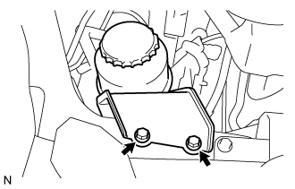
Install the vane pump oil reservoir assembly with the 2 bolts.
- Torque:
- 8.0 N*m { 82 kgf*cm, 71 in.*lbf }
-
-
INSTALL TIMING BELT
-
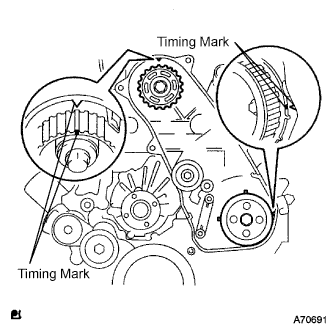
Check that the timing marks are aligned as shown in the illustration.
-
Install the timing belt to pump drive shaft pulley, camshaft timing pulley and timing belt idler No.1 in sequence.
-
Set the tensioner to the press upright.
Note
-
Do not allow the rod end to scratch and deform.
-
Press the tensioner rod in upward.
-
Protect a tip of the push rod with a rag in order to prevent damage.
-
-
Using a press, slowly apply 981 to 9,807 N (100 to 1,000 kgf, 220 to 2,205 lbf) of force to the push rod.
Note
Do not apply loads 981 to 9,807 N (100 to 1,000 kgf, 220 to 2,205 lbf) or more on the push rod.
-
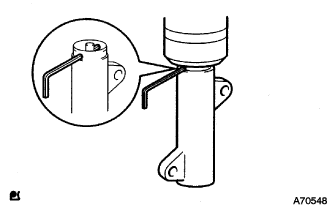
Align the holes of push rod and housing, pass a 1.27 mm hexagon wrench through the holes to keep the setting position of the push rod.
-
Temporarily install the timing belt tensioner with the 2 bolts while pushing the idler pulley toward the timing belt.
-
Tighten the 2 bolts.
- Torque:
- 13 N*m { 133 kgf*cm, 10 ft.*lbf }
Note
Uniformly tighten the 2 bolts and install the tensioner
-
Remove the 1.5 mm hexagon wrench from the tensioner.
-
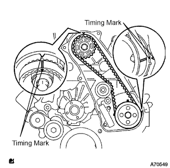
Turn the crankshaft in the clockwise direction twice, check that the timing marks are aligned as shown in the illustration.
-
-
INSTALL TIMING BELT COVER NO.1
-
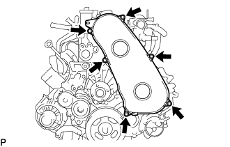
Install the timing belt No.1 cover with the 6 bolts.
- Torque:
- 6.0 N*m { 61 kgf*cm, 53 in.*lbf }
-
Install the wire harness clamp.
-
-
INSTALL FAN & GENERATOR V BELT
-
Rotate the V-ribbed belt tensioner pulley clockwise, and then install the fan and generator V belt.
Note
Make sure that the fan and generator V belt is set properly on each pulley.
-
Check that the indicator mark of the V-ribbed belt tensioner Click here.
-
-
INSTALL ENGINE SERVICE HOLE SUB COVER SUB-ASSEMBLY
-
Install the engine service hole sub cover with the 5 bolts.
- Torque:
- 13 N*m { 133 kgf*cm, 10 ft.*lbf }
-
-
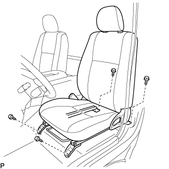
INSTALL FRONT SEAT ASSEMBLY RH (for Hi-back Seat Type)
-
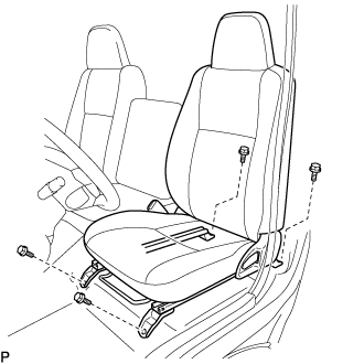
Connect the front seat inner belt assembly connector and install the front seat assembly.
-
Align the front seat assembly adjuster pin with the holes in the body.
-
Move the front seat assembly to the rearmost position.
Note
Make sure that the front seat assembly is securely locked.
-
Temporarily tighten the 2 bolts on the front side of the front seat assembly.
-
Move the front seat assembly fully forward.
Note
Make sure that the front seat assembly is securely locked.
-
Temporarily tighten the 2 bolts on the rear side of the front seat assembly.
-
Move the front seat assembly to the rearmost position.
Note
Make sure that the front seat assembly is securely locked.
-
Fully tighten the 2 bolts on the front side of the front seat assembly in the order of outer and inner side.
- Torque:
- 39 N*m { 398 kgf*cm, 29 ft.*lbf }
-
Move the front seat assembly fully forward.
Note
Make sure that the front seat assembly is securely locked.
-
Fully tighten the 2 bolts on the rear side of the front seat assembly in the order of outer and inner side.
- Torque:
- 39 N*m { 398 kgf*cm, 29 ft.*lbf }
-
-
INSTALL FRONT SEAT ASSEMBLY RH (for Low-back Seat Type)
-
Connect the front seat inner belt assembly connector and install the front seat assembly.
-
Align the front seat assembly adjuster pin with the holes in the body.
-
Move the front seat assembly to the rearmost position.
Note
Make sure that the front seat assembly is securely locked.
-
Temporarily tighten the 2 bolts on the front side of the front seat assembly.
-
Move the front seat assembly fully forward.
Note
Make sure that the front seat assembly is securely locked.
-
Temporarily tighten the 2 bolts on the rear side of the front seat assembly.
-
Move the front seat assembly to the rearmost position.
Note
Make sure that the front seat assembly is securely locked.
-
Fully tighten the 2 bolts on the front side of the front seat assembly in the order of outer and inner side.
- Torque:
- 39 N*m { 398 kgf*cm, 29 ft.*lbf }
-
Move the front seat assembly fully forward.
Note
Make sure that the front seat assembly is securely locked.
-
Fully tighten the 2 bolts on the rear side of the front seat assembly in the order of outer and inner side.
- Torque:
- 39 N*m { 398 kgf*cm, 29 ft.*lbf }
-
-
INSTALL FRONT DOOR SCUFF PLATE RH
-
CONNECT BATTERY NEGATIVE CABLE
-
BLEED FUEL LINE
-
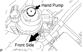
Using the hand pump, bleed air from the fuel system until pumping becomes difficult.
-
-
CHECK FOR FUEL LEAKAGE
-
PERFORM ACTIVE TEST
-
Connect the GTS to the DLC3.
-
Turn the ignition switch on.
-
Turn the GTS on.
-
Enter the following menus: Powertrain / Engine and ECT / Active Test.
-
Perform the Active Test.
Tester Display Test Details Control Range Diagnostic Notes Test the Fuel Leak Pressurizes common rail internal fuel pressure, and checks for fuel leaks Stop/Start
-
Fuel pressure inside common rail pressurized to specified value and engine speed increased to 2,000 rpm when ON is selected
-
Above conditions preserved while test is ON
-
-
-