FUEL TEMPERATURE SENSOR REMOVAL

-
REMOVE BATTERY SERVICE HOLE COVER (w/ Sub-Battery)
-
DISCONNECT BATTERY NEGATIVE CABLE
-
REMOVE FRONT SEAT ASSEMBLY RH (for Hi-back Seat Type)
-
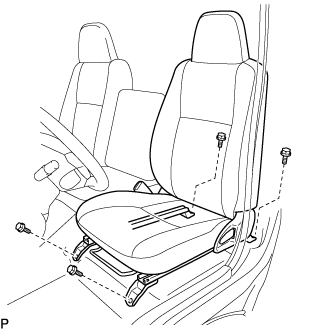
Move the front seat assembly fully forward.
-
Remove the 2 bolts on the rear side of the seat.
-
Move the front seat assembly to the rearmost position.
-
Remove the 2 bolts on the front side of the seat.
-
Move the front seat assembly to the center of the seat slide rail. Set the seatback in the upright position.
-
Disconnect the front seat inner belt assembly connector.
-
Remove the front seat assembly.
-
-
REMOVE FRONT SEAT ASSEMBLY RH (for Low-back Seat Type)
-
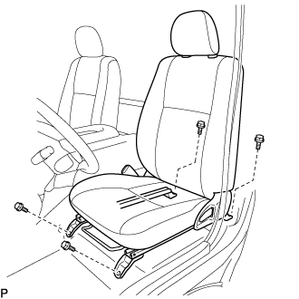
Move the front seat assembly fully forward.
-
Remove the 2 bolts on the rear side of the seat.
-
Move the front seat assembly to the rearmost position.
-
Remove the 2 bolts on the front side of the seat.
-
Move the front seat assembly to the center of the seat slide rail. Set the seatback in the upright position.
-
Disconnect the front seat inner belt assembly connector.
-
Remove the front seat assembly.
-
-
REMOVE FRONT DOOR SCUFF PLATE RH
-
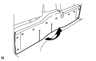
REMOVE ENGINE SERVICE HOLE SUB COVER SUB-ASSEMBLY
-
Roll up the carpet, and remove the engine service hole sub cover assembly.
-
-
REMOVE FAN & GENERATOR V BELT
-
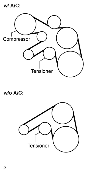
Remove the drive belt by rotating the tensioner pulley in clockwise direction to loosen its tension with the pulley set bolt of the tensioner.
-
-
SET NO.1 CYLINDER TO TDC/ COMPRESSION
-
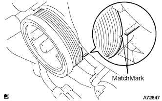
Align the matchmarks of the crankshaft pulley and timing gear case cover by rotating the crankshaft in clockwise direction.
Tech Tips
Make sure that both camnoses on the intake side and exhaust side of the cylinder No.1 face upward.
-
-
REMOVE TIMING BELT COVER NO.1
-
Remove the wire harness clamp.
-
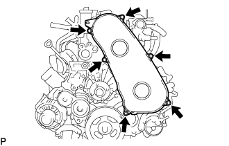
Remove the 6 bolts and timing belt cover No.1.
-
-
REMOVE TIMING BELT
-
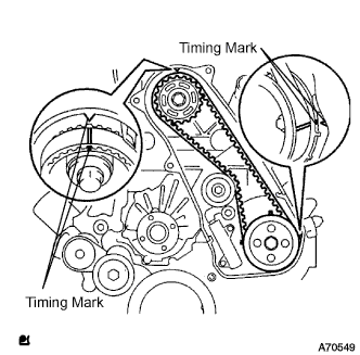
Turn the crankshaft in the clockwise direction and align the timing marks as shown in the illustration.
-
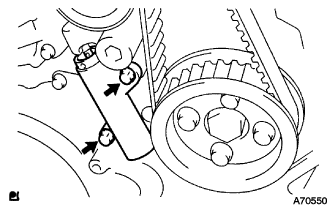
Uniformly loosen the 2 bolts, and remove the chain tensioner assembly No.1.
-
Remove the timing belt.
-
-
DISCONNECT VANE PUMP OIL RESERVOIR ASSEMBLY
-
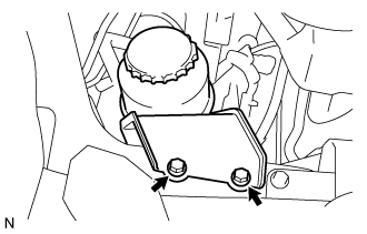
Remove the 2 bolts. Separate the vane pump oil reservoir assembly.
-
-
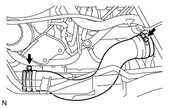
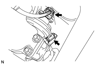
DISCONNECT OIL RETURN HOSE (w/ Inter Cooler)
-
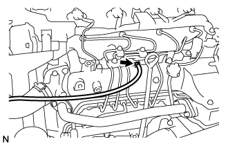
Loosen the clip.
-
Disconnect the oil return hose from the intake manifold.
-
-
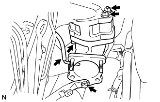
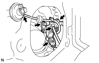
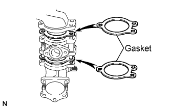
REMOVE EGR PIPE SUB-ASSEMBLY NO.1 (w/ EGR Valve)
-
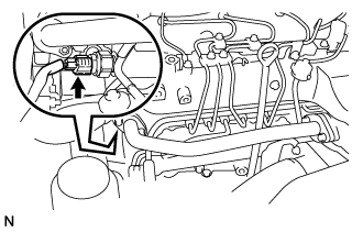
Disconnect the fuel pressure sensor connector.
-
Remove the 2 bolts, 2 nuts, and the EGR pipe sub-assembly.
-
Remove the 2 gaskets.
-
-
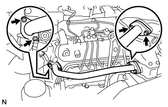
REMOVE AIR HOSE NO.4
-
Loosen the 2 clamps.
-
Remove the air hose No.4.
-
-
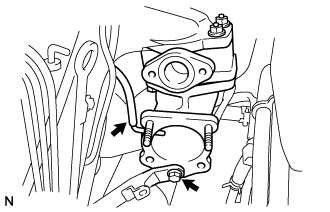
REMOVE DIESEL THROTTLE BODY ASSEMBLY
-
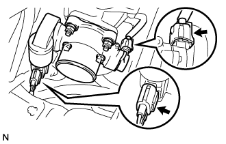
Disconnect the 2 throttle body connectors.
-
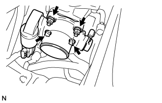
Remove the 2 bolts, 2 nuts, and the diesel throttle body assembly.
-
Remove the gasket from intake air connector.
-
-
REMOVE ENGINE SERVICE HOLE COVER NO.2
-
Roll up the carpet.
-
Remove the 3 bolts and the engine service hole cover No.2.
-
-
REMOVE INTAKE AIR CONNECTOR (w/o EGR Valve)
-
Remove the bolt, and separate the manifold stay.
-
Disconnect the vacuum hose from intake air connector.
-
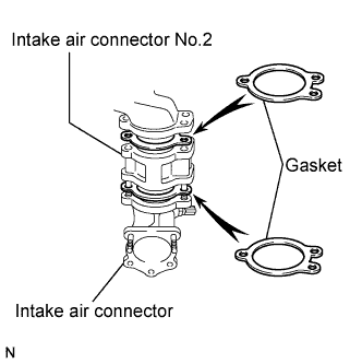
Remove the bolt, 2 nuts and the intake air connector assembly.
-
Remove the 2 gaskets and intake air connector No.2 from the intake air connector.
-
-
REMOVE ELECTRIC EGR CONTROL VALVE ASSEMBLY (w/ EGR Valve)
-
Remove the vacuum regulating valve.
-
Remove the 2 vacuum hoses and the vacuum regulating valve connector.
-
Remove the 2 bolts and the vacuum regulating valve.
-
-
Remove the EGR valve assembly with the sensor.
-
Remove the bolt, and separate the manifold stay.
-
Disconnect the vacuum hose from the intake air connector.
-
Disconnect the intake air temperature sensor connector.
-
Disconnect the EGR valve position sensor connector.
-
Remove the bolt, 2 nuts and the intake air connector assembly.
-
Remove the 2 gaskets and EGR valve assembly from the intake air connector.
-
-
-
REMOVE OIL LEVEL GAGE GUIDE
-
Remove the oil level gauge.
-
Remove the bolt and oil level gauge guide.
-
-
REMOVE INJECTION PIPE
- SST
- 09023-12701
-
Remove the injection pipe.
-
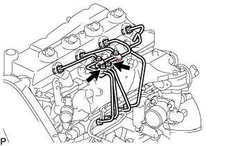
Remove the 2 nuts and injection pipe clamp No.3.
-
Using SST, remove the 4 injection pipes.
- SST
- 09023-12701
-
-
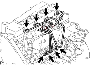
REMOVE FUEL INLET PIPE SUB-ASSEMBLY
-
Using SST, remove the fuel inlet pipe sub-assembly.
- SST
- 09023-12701
-
-
REMOVE INJECTION OR SUPPLY PUMP ASSEMBLY
-
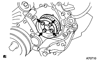
Remove the 4 bolts.
-
Remove the camshaft timing pulley flange No.2 and pump drive shaft pulley.
-
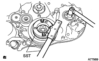
Using SST, remove the supply pump gear set nut and O-ring while holding the crankshaft pulley.
- SST
- 09213-58013
- 09330-00021
-
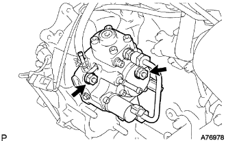
Disconnect the 2 fuel hoses.
-
Disconnect the 2 connectors and wire harness.
-
Loosen the 2 nuts as shown in the illustration.
-
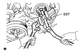
Using SST, disengage the supply pump from the supply pump gear.
- SST
- 09950-50013 ( 09951-05010, 09952-05010, 09953-05020, 09954-05021 )
-
Remove the 2 nuts and supply pump from the engine.
-
Remove the O-ring from the supply pump.
-
Remove the pulley key from the supply pump.
-
-
REMOVE FUEL TEMPERATURE SENSOR
-
Mount the injection or supply pump assembly in a soft jaw vise.
-
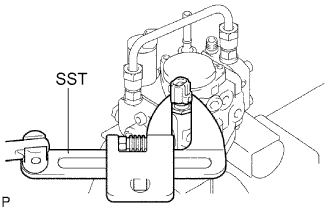
Using a SST, remove the fuel temperature sensor.
- SST
- 09922-10010
-
Remove the O-ring form the fuel temperature sensor.
-