FUEL INJECTOR INSTALLATION
Note
-
When replacing the parts in the following chart (A), replace the No. 1 injection pipe sub-assembly, No. 2 injection pipe sub-assembly and/or fuel inlet pipe sub-assembly with new ones.
Replaced Parts (A) Pipes Requiring New Replacement
-
Injector assembly (including shuffling the injector assemblies between the cylinders)
-
Common rail assembly
-
Cylinder head sub-assembly
-
No. 1 injection pipe sub-assembly
-
No. 2 injection pipe sub-assembly
Supply pump assembly Fuel inlet pipe sub-assembly
-
Common rail assembly
-
Cylinder block sub-assembly
-
Cylinder head sub-assembly
-
Cylinder head gasket
-
Timing chain case assembly
-
No. 1 injection pipe sub-assembly
-
No. 2 injection pipe sub-assembly
-
Fuel inlet pipe sub-assembly
-
-
After removing the No. 1 injection pipe sub-assembly, No. 2 injection pipe sub-assembly and/or fuel inlet pipe sub-assembly, clean them with a brush and compressed air.
-
The injector assembly is a precision instrument. Do not use the injector assembly if it is struck or dropped.
-
Make sure foreign matter does not enter the fuel path.
-
INSTALL NOZZLE HOLDER GASKET
-
Install 4 new nozzle holder gaskets to the cylinder head cover sub-assembly.
-
-
TEMPORARILY INSTALL INJECTOR ASSEMBLY
Tech Tips
Before installing the injector assembly, check for carbon, foreign matter, etc. on the seal surfaces of the cylinder head sub-assembly and injector assembly. If there is foreign matter, remove it before installing the injector assembly.
-
Install 4 new injection nozzle seats to the cylinder head sub-assembly.
-
Apply a light coat of engine oil to the O-ring on each injector assembly.
-
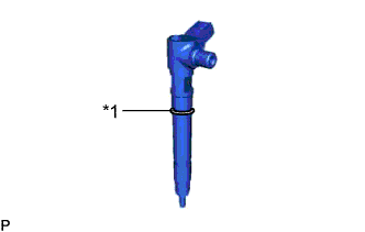
Text in Illustration *1 O-Ring Install a new O-ring to each injector assembly.
-
Install the 4 injector assemblies to the cylinder head sub-assembly.
Note
Fit the injector assembly to the injection nozzle seats.
-
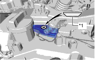
Text in Illustration *1 Washer Install the nozzle holder clamps and washers as shown in the illustration.
Note
Pay attention to the mounting orientation (beveled edge) of the washer.
-
Temporarily install the nozzle holder clamp bolts.
Note
When temporarily installing the nozzle holder clamp bolt to the No. 1 nozzle holder clamp, make sure that the bolt and clamp are not at an angle.
Tech Tips
Apply a light coat of engine oil to the threads of the nozzle holder clamp bolts.
-
-
TEMPORARILY INSTALL NO. 1 AND NO. 2 INJECTION PIPE SUB-ASSEMBLY
-
Temporarily install the 2 No. 2 injection pipe sub-assemblies with the 4 union nuts.
-
Temporarily install the 2 No. 1 injection pipe sub-assemblies with the 4 union nuts.
-
-
TIGHTEN INJECTOR ASSEMBLY
-
Tighten the 4 nozzle holder clamp bolts.
- Torque:
- 21 N*m { 214 kgf*cm, 15 ft.*lbf }
-
-
TIGHTEN NO. 1 AND NO. 2 INJECTION PIPE SUB-ASSEMBLY
-
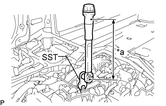
Text in Illustration *a Torque Wrench Fulcrum Length Using SST, tighten the 8 union nuts of the No. 1 and No. 2 injection pipe sub-assemblies.
- Torque:
- Specified tightening torque
- 40 N*m { 408 kgf*cm, 30 ft.*lbf }
Tech Tips
-
Calculate the torque wrench reading when changing the fulcrum length of the torque wrench.
-
When using SST (fulcrum length of 50 mm (1.97 in.)) + torque wrench (fulcrum length of 180 mm (7.09 in.)): 31 N*m (316 kgf*cm, 23 ft.*lbf)
-
-
INSTALL NOZZLE LEAKAGE PIPE ASSEMBLY
-
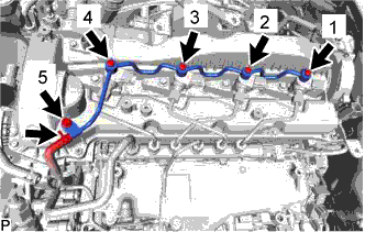
Temporarily install the nozzle leakage pipe assembly and 4 new gaskets with the 4 union bolts and bolt.
-
Tighten the 4 union bolts and bolt in the order shown in the illustration.
- Torque:
- 10 N*m { 102 kgf*cm, 7 ft.*lbf }
-
Connect the No. 5 fuel hose to the nozzle leakage pipe assembly.
-
-
INSTALL HARNESS BRACKET
-
Install the harness bracket with the bolt.
- Torque:
- 10 N*m { 102 kgf*cm, 7 ft.*lbf }
-
-
INSTALL NO. 2 WATER BY-PASS PIPE
-
Connect the heater hose to the No. 2 water by-pass pipe.
-
Install the No. 2 water by-pass pipe with the 2 bolts.
- Torque:
- 10 N*m { 102 kgf*cm, 7 ft.*lbf }
-
-
INSTALL WIRING HARNESS CLAMP BRACKET
-
Install the wiring harness clamp bracket the cylinder head cover sub-assembly with the bolt.
- Torque:
- 10 N*m { 102 kgf*cm, 7 ft.*lbf }
-
Connect the pressure discharge valve connector to the common rail assembly.
-
-
INSTALL NO. 1 FUEL PIPE
-
Connect the No. 1 fuel pipe to the No. 4 fuel pipe.
-
Install a new gasket and the No. 1 fuel pipe to the cylinder head cover sub-assembly and No. 1 injector holder with the union bolt and bolt.
- Torque:
- for bolt
- 10 N*m { 102 kgf*cm, 7 ft.*lbf }
- for union bolt
- 36 N*m { 367 kgf*cm, 27 ft.*lbf }
-
-
INSTALL EGR COOLER ASSEMBLY
-
CONNECT CABLE TO NEGATIVE BATTERY TERMINAL
Note
When disconnecting the cable, some systems need to be initialized after the cable is reconnected Click here.
-
PERFORM REGISTRATION
-
Perform registration of injector compensation codes Click here.
-
Perform registration of pilot quantity learning Click here.
-
-
BLEED AIR FROM FUEL SYSTEM
-
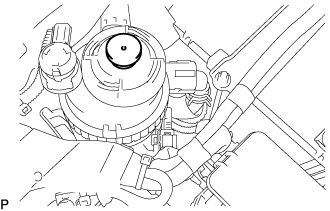
Using the hand pump mounted on the fuel filter cap, bleed air from the fuel system. Continue pumping until the pump resistance increases.
Note
-
The maximum hand pump pumping speed is 2 strokes per second.
-
The hand pump must be pushed with a full stroke during pumping.
-
When the fuel pressure at the supply pump inlet port reaches a saturated pressure, the hand pump resistance increases.
-
If pumping is interrupted during the air bleeding process, fuel in the fuel line may return to the fuel tank. Continue pumping until the hand pump resistance increases.
-
If the hand pump resistance does not increase despite consecutively pumping 200 times or more, there may be a fuel leak between the fuel tank and fuel filter, the hand pump may be malfunctioning, or the vehicle may have run out of fuel.
-
If air bleeding using the hand pump is incomplete, the common rail pressure does not rise to the pressure range necessary for normal use and the engine cannot be started.
-
-
Check if the engine starts.
Note
-
Even if air bleeding using the hand pump has been completed, the starter may need to be cranked for 10 seconds or more to start the engine.
-
Do not crank the engine continuously for more than 20 seconds. The battery may be discharged.
-
Use a fully-charged battery.
-
When the engine can be started, proceed to the next step.
-
If the engine cannot be started, bleed air again using the hand pump until the hand pump resistance increases (refer to the procedures above). Then start the engine.
-
-
Turn the ignition switch off.
-
Connect the GTS to the DLC3.
-
Turn the ignition switch to ON and turn the GTS on.
-
Clear the DTCs Click here.
-
Start the engine.*1
-
Enter the following menus: Powertrain / Engine and ECT / Active Test / Test the Fuel Leak.*2
-
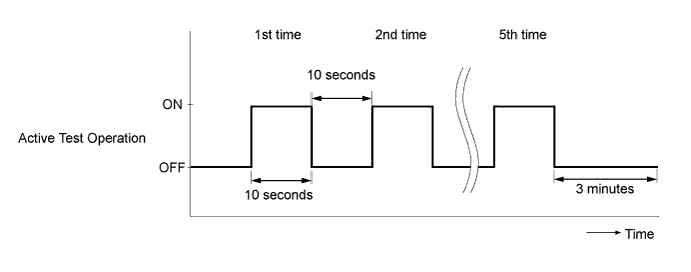
Perform the following test 5 times with on/off intervals of 10 seconds: Active Test / Test the Fuel Leak.*3
-
Allow the engine to idle for 3 minutes or more after performing the Active Test for the 5th time.
Tech Tips
When the Active Test "Test the Fuel Leak" is used to change the pump control mode, the actual fuel pressure inside the common rail drops below the target fuel pressure when the Active Test is off, but this is normal and does not indicate a pump malfunction.
-
Enter the following menus: Powertrain / Engine and ECT /Trouble Codes.
-
Read Current DTCs.
-
Clear the DTCs Click here.
Tech Tips
It is necessary to clear the DTCs as DTC P1604 or P1605 may be stored when air is bled from the fuel system after replacing or repairing fuel system parts.
-
Repeat steps *1 to *3.
-
Enter the following menus: Powertrain / Engine and ECT / Trouble Codes.
-
Read Current DTCs.
OK No DTCs are output.
-
-
INSPECT FOR FUEL LEAK
Note
-
During Active Test mode, the engine speed becomes high and the combustion noise becomes loud, so pay attention.
-
During Active Test mode, the fuel pressure becomes high. Be extremely careful not to expose your eyes, hands, or body to escaping fuel.
Tech Tips
Using the GTS to perform Active Tests allow relays, VSVs, actuators and other items to be operated without removing any parts. This non-intrusive functional inspection can be very useful because intermittent operation may be discovered before parts or wiring is disturbed. Performing Active Tests early in troubleshooting is one way to save diagnostic time. Data List information can be displayed while performing Active Tests.
-
Check that there are no leaks from any part of the fuel system when the engine is stopped. If there is fuel leakage, repair or replace parts as necessary.
-
Start the engine and check that there are no leaks from any part of the fuel system. If there is fuel leakage, repair or replace parts as necessary.
-
Disconnect the return hose from the common rail assembly.
-
Start the engine and check for fuel leaks from the return pipe. If there is fuel leakage, replace the common rail assembly.
-
Perform the Active Test.
-
Connect the GTS to the DLC3.
-
Turn the ignition switch to ON.
-
Turn the GTS on.
-
Enter the following menus: Powertrain / Engine / Active Test / Test the Fuel Leak.
-
If the GTS is not available, fully depress the accelerator pedal quickly. Increase the engine speed to the maximum and maintain that speed for 2 seconds. Repeat this operation several times.
-
Check that there are no leaks from any part of the fuel system.
Tech Tips
A return pipe leakage of less than 10 cc (0.6 cu in.) per minute is acceptable.
If there is fuel leakage, repair or replace parts as necessary.
-
-
Reconnect the return hose to the common rail assembly.
-