CAMSHAFT INSPECTION

-
INSTALL CAMSHAFT TIMING GEAR ASSEMBLY
-
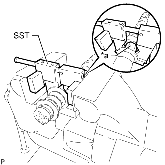
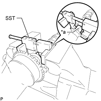
Text in Illustration *a Hexagonal Portion Using SST, grip the hexagonal portion, and then secure the SST and camshaft in a vise as shown in the illustration.
- SST
- 09212-31010
Note
-
Do not damage the camshaft.
-
Never grip areas other than the hexagonal portion, as this may cause damage.
-
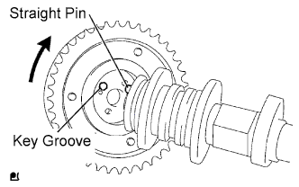
Put the camshaft timing gear and camshaft together by aligning the key groove and straight pin.
-
Lightly press the gear against the camshaft, and turn the gear. Push further at the position where the pin enters the groove.
Note
Be sure not to turn the camshaft timing gear in the retard direction (the right angle).
-
Check that there is no clearance between the gear's flange and the camshaft.
Note
-
Since the thrust clearance of the camshaft is small, the camshaft must be kept level while it is being removed. If the camshaft is not kept level, the portion of the cylinder head receiving the shaft thrust may crack or be damaged, causing the camshaft to seize or break.
-
Be sure not to remove the other 3 bolts. If removing the bolts, exchange the camshaft timing gear assembly.
-
-
Tighten the flange bolt with the camshaft timing gear fixed.
- Torque:
- 78 N*m { 795 kgf*cm, 59 ft.*lbf }
-
Check that the camshaft timing gear assembly can move in the retard direction (the right angle), and is locked at the most retarded position.
-
-
INSPECT CAMSHAFT TIMING GEAR ASSEMBLY
-
Check the lock of the camshaft timing gear.
-
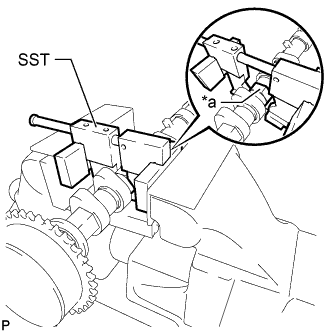
Text in Illustration *a Hexagonal Portion Using SST, grip the hexagonal portion, and then secure the SST and camshaft in a vise as shown in the illustration and check that the camshaft timing gear assembly does not rotate.
- SST
- 09212-31010
Note
-
Do not damage the camshaft.
-
Never grip areas other than the hexagonal portion, as this may cause damage.
-
-
Release the lock pin.
-
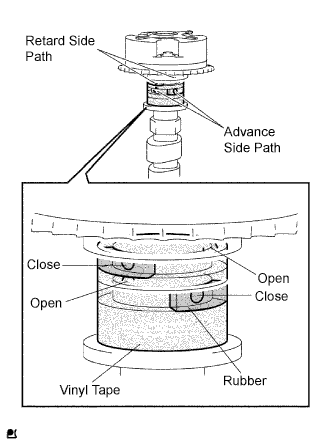
Cover the 4 oil paths of the cam journal with vinyl tape as shown in the illustration.
Tech Tips
2 advance side paths are provided in the groove of the camshaft. Plug one of the paths with a rubber piece.
-
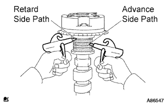
Break through the tape of the advance side path and the retard side path on the opposite side to the hole of the advance side path.
-
Apply approximately 200 kPa (2.0 kgf/cm2, 28 psi) of air pressure to the two broken paths.
Note
Some oil splashing will occur. Cover the paths with a shop rag or a piece of cloth.
-
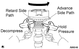
Check that the camshaft timing gear revolves in the advance direction when reducing the air pressure applied to the retard side path.
OK Gear rotates in the advance direction. Tech Tips
This operation releases the lock pin for the most retarded position.
-
When the camshaft timing gear reaches the most advanced position, release the air pressure from the retard side path and advance side path, in that order.
Note
Do not release the air pressure from the advance side path first. The gear may abruptly shift in the retard direction and break the lock pin.
-
-
Check for smooth rotation.
-
Rotate the camshaft timing gear within its movable range several times, but do not turn it to the most retarded position. Check that the gear rotates smoothly.
OK Gear rotates in the advance direction. Note
Do not use air pressure to perform the smooth operation check.
-
-
Check the lock in the most retarded position.
-
Confirm that the camshaft timing gear is locked at the most retarded position.
-
-
-
REMOVE CAMSHAFT TIMING GEAR ASSEMBLY
-
Text in Illustration *a Hexagonal Portion Using SST, grip the hexagonal portion, and then secure the SST and camshaft in a vise as shown in the illustration.
- SST
- 09212-31010
Note
-
Do not damage the camshaft.
-
Never grip areas other than the hexagonal portion, as this may cause damage.
-
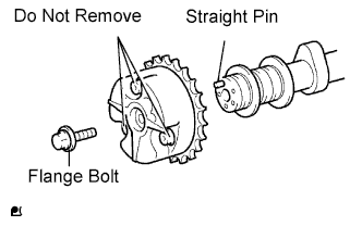
Remove the flange bolt and camshaft timing gear.
Note
-
Be sure not to remove the other 3 bolts.
-
If planning to reuse the gear, be sure to release the straight pin lock before installing the gear.
-
-