ENGINE UNIT DISASSEMBLY

-
REMOVE OIL FILLER CAP SUB-ASSEMBLY
-
REMOVE PCV VALVE SUB-ASSEMBLY
-
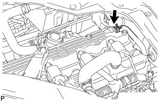
Slide the clamp and disconnect the PCV hose from the PCV valve sub-assembly.
-
Remove the PCV valve sub-assembly.
-
-
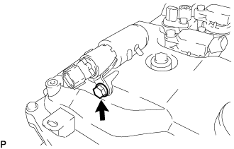
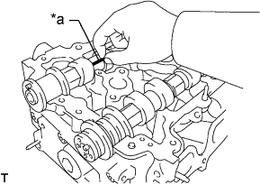
REMOVE CAMSHAFT POSITION SENSOR
-
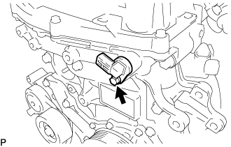
for Intake Side:
-
Disconnect the camshaft position sensor connector.
-
Remove the bolt and camshaft position sensor.
-
-
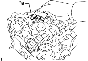
for Exhaust Side:
-
Disconnect the camshaft position sensor connector.
-
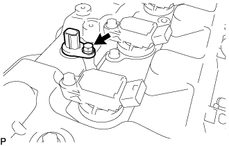
Remove the bolt and camshaft position sensor.
-
-
-
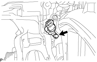
REMOVE CRANKSHAFT POSITION SENSOR
-
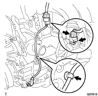
Disconnect the crankshaft position sensor connector and detach the 2 wire harness clamps.
-

Remove the bolt and crankshaft position sensor.
-
-
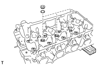
REMOVE CAMSHAFT TIMING OIL CONTROL VALVE ASSEMBLY
-
for Intake Side:
-
Disconnect the camshaft timing oil control valve connector.
-
Remove the bolt and camshaft timing oil control valve assembly from the cylinder head sub-assembly.
-
Remove the O-ring from the camshaft timing oil control valve assembly.
-
-
for Exhaust Side:
-
Disconnect the camshaft timing oil control valve connector.
-
Remove the bolt and camshaft timing oil control valve assembly from the cylinder head cover sub-assembly.
-
Remove the O-ring from the camshaft timing oil control valve assembly.
-
-
-
REMOVE CYLINDER HEAD COVER SUB-ASSEMBLY
-
Slide the clip and disconnect the PCV hose from the PCV valve sub-assembly.
-
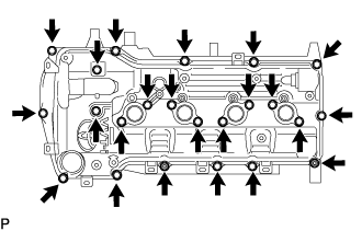
Remove the 21 bolts, 2 nuts, 2 plate washers, 2 seal washers and cylinder head cover sub-assembly.
-
Remove the gasket from the cylinder head cover sub-assembly.
-
Remove the No. 1 camshaft bearing cap oil hole gasket from the cylinder head cover spacer.
-
-
REMOVE NO. 1 VENTILATION CONNECTOR
-
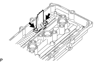
Remove the 2 bolts and No. 1 ventilation connector from the cylinder head cover sub-assembly.
-
-
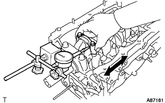
REMOVE CRANKSHAFT PULLEY
-
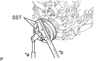
Text in Illustration *a Loosen *b Hold Using SST, hold the crankshaft pulley and loosen the crankshaft pulley set bolt.
- SST
- 09213-54015 ( 91651-60855 )
- 09330-00021
-
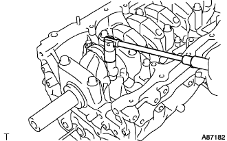
Screw the crankshaft pulley set bolt into the crankshaft by 2 or 3 threads.
-
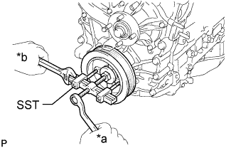
Text in Illustration *a Loosen *b Hold Using the crankshaft pulley set bolt and SST, remove the crankshaft pulley.
- SST
- 09213-54015 ( 91651-60855 )
- 09330-00021
- 09950-50013 ( 09951-05010, 09952-05010, 09953-05010, 09954-05021 )
Tech Tips
Apply lubricant to the threads and end of SST.
-
-
REMOVE NO. 2 OIL PAN SUB-ASSEMBLY
-
Remove the oil pan drain plug and gasket.
-
Remove the 18 bolts and 2 nuts.
-
Insert the blade of an oil pan seal cutter between the oil pan sub-assembly and No. 2 oil pan sub-assembly. Cut through the applied sealer and remove the No. 2 oil pan sub-assembly.
Note
Be careful not to damage the contact surfaces of the oil pan sub-assembly and No. 2 oil pan sub-assembly.
-
-
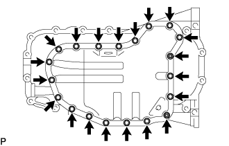
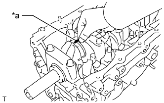
REMOVE OIL PAN SUB-ASSEMBLY
-

Remove the 16 bolts and 2 nuts.
-

Text in Illustration *a Protective Tape Using a screwdriver wrapped in protective tape, remove the oil pan sub-assembly by prying between the oil pan sub-assembly and cylinder block sub-assembly as shown in the illustration.
Note
Be careful not to damage the contact surfaces of the cylinder block sub-assembly and oil pan sub-assembly.
Tech Tips
Tape the screwdriver tip before use.
-
Remove the gasket.
-
-
REMOVE OIL STRAINER SUB-ASSEMBLY
-
Remove the 6 bolts and oil strainer sub-assembly.
-
-
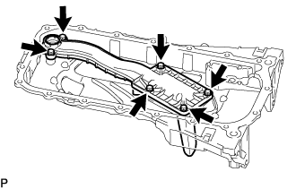
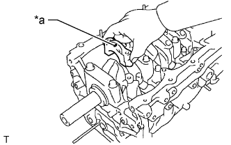
REMOVE TIMING CHAIN OR BELT COVER SUB-ASSEMBLY
-
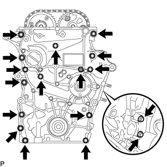
Remove the 16 bolts and nut shown in the illustration.
-
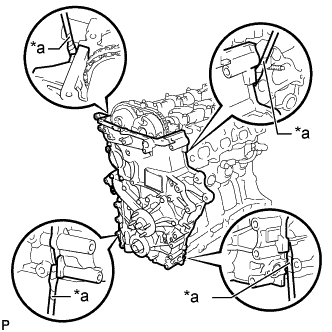
Text in Illustration *a Protective Tape Using a screwdriver wrapped in protective tape, remove the timing chain or belt cover sub-assembly by prying the points in the illustration.
Note
Do not damage the surrounding parts.
Tech Tips
Tape the screwdriver tip before use.
-
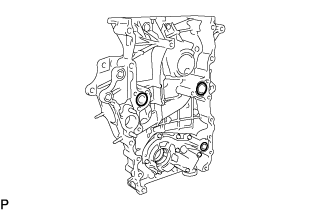
Remove the 3 O-rings from the timing chain or belt cover sub-assembly.
-
-
REMOVE ENGINE WATER PUMP ASSEMBLY
-
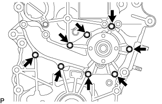
Remove the 8 bolts, engine water pump assembly and gasket from the timing chain or belt cover sub-assembly.
-
-
REMOVE TIMING CHAIN CASE OIL SEAL
-
Text in Illustration *a Protective Tape Using a screwdriver wrapped in protective tape, pry out the timing chain case oil seal from the timing chain or belt cover sub-assembly.
Note
Be careful not to damage the timing chain or belt cover sub-assembly.
Tech Tips
Tape the screwdriver tip before use.
-
-
SET NO. 1 CYLINDER TO TDC/COMPRESSION
-
Temporarily install the crankshaft pulley bolt.
-
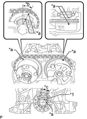
Text in Illustration *1 Key *a Timing Mark *b Approximately 13° *c Approximately 30° Rotate the crankshaft clockwise so that the timing marks on the crankshaft timing gear and camshaft timing gears are as shown in the illustration.
Tech Tips
If the timing marks do not align, rotate the crankshaft clockwise again and align the timing marks.
-
Remove the crankshaft pulley bolt.
-
-
REMOVE CYLINDER HEAD COVER CONNECTOR SUB-ASSEMBLY
-
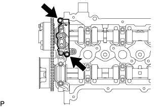
Remove the 2 bolts and cylinder head cover connector sub-assembly.
-
Remove the No. 2 camshaft bearing cap oil hole gasket and 3 No. 3 camshaft bearing cap oil hole gaskets from the camshaft bearing cap.
-
-
REMOVE TIMING CHAIN GUIDE
-
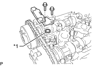
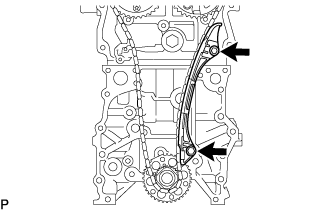
Text in Illustration *1 O-Ring Remove the 2 bolts, timing chain guide and O-ring.
-
-
REMOVE NO. 1 CHAIN TENSIONER ASSEMBLY
Note
-
When the No. 1 chain tensioner assembly is removed, do not rotate the crankshaft.
-
When the chain is removed and the camshaft needs to be rotated, rotate the crankshaft 90° to the right.
-
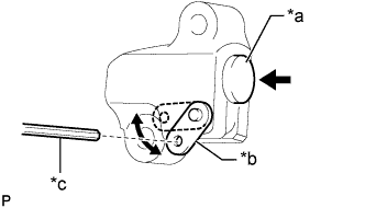
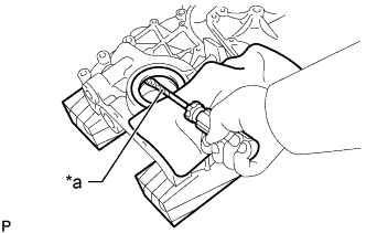
Text in Illustration *a Plunger *b Stopper Plate *c Hexagon Wrench Move the stopper plate upward to release the lock and push the plunger deep into the tensioner.
-
Move the stopper plate downward to set the lock and insert a hexagon wrench into the stopper plate hole.
-
Remove the bolt, nut, No. 1 chain tensioner assembly and gasket.
-
-
REMOVE CHAIN TENSIONER SLIPPER
-
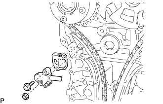
Remove the bolt and chain tensioner slipper.
-
-
REMOVE NO. 1 CHAIN VIBRATION DAMPER
-
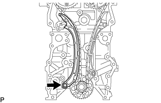
Remove the 2 bolts and No. 1 chain vibration damper.
-
-
REMOVE CHAIN SUB-ASSEMBLY
-
REMOVE CRANKSHAFT TIMING GEAR OR SPROCKET
-
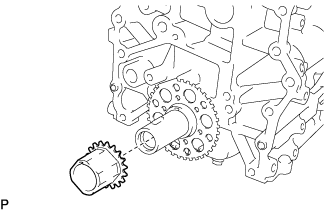
Remove the crankshaft timing gear or sprocket from the crankshaft.
-
-
REMOVE CRANK POSITION SENSOR ROTOR
-
REMOVE CRANKSHAFT PULLEY SET KEY
-
Remove the 2 crankshaft pulley set keys from the crankshaft.
-
-
REMOVE OIL JET
-
Remove the bolt, oil jet and gasket.
-
-
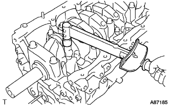
REMOVE CAMSHAFT BEARING CAP
-
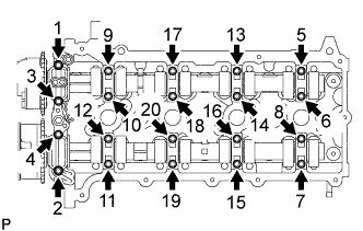
Uniformly loosen and remove the 20 bearing cap bolts in the sequence shown in the illustration.
Note
Uniformly loosen the bolts while keeping the camshafts level.
-
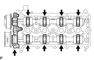
Remove the 9 bearing caps.
Tech Tips
Arrange the removed parts in the correct order.
-
-
REMOVE CAMSHAFT
-
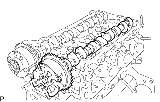
Remove the camshaft.
-
-
REMOVE NO. 2 CAMSHAFT
-
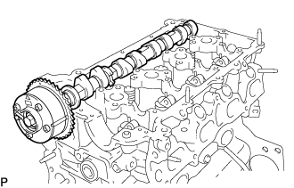
Remove the No. 2 camshaft.
-
-
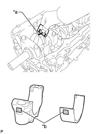
REMOVE NO. 1 VALVE ROCKER ARM SUB-ASSEMBLY
-
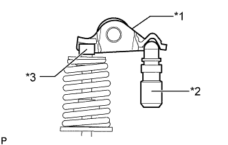
Text in Illustration *1 No. 1 Valve Rocker Arm Sub-assembly *2 Valve Lash Adjuster Assembly *3 Valve Stem Cap Remove the 16 No. 1 valve rocker arm sub-assemblies from the cylinder head sub-assembly.
Tech Tips
Arrange the removed parts in the correct order.
-
-
REMOVE VALVE STEM CAP
-
Remove the 16 valve stem caps from the cylinder head sub-assembly.
Tech Tips
Arrange the removed parts in the correct order.
-
-
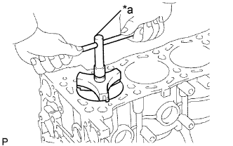
REMOVE VALVE LASH ADJUSTER ASSEMBLY
-
Remove the 16 valve lash adjuster assemblies from the cylinder head sub-assembly.
Tech Tips
Arrange the removed parts in the correct order.
-
-
INSPECT CAMSHAFT TIMING GEAR ASSEMBLY
-
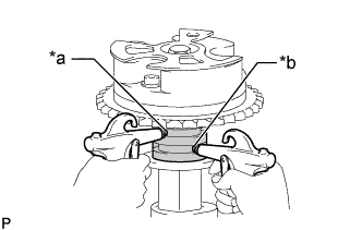
Check the lock of the camshaft timing gear assembly.
-
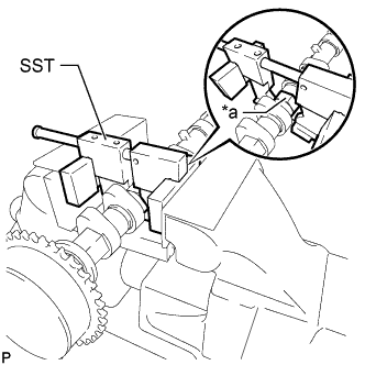
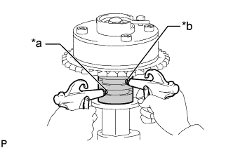
Text in Illustration *a Hexagonal Portion Using SST, grip the hexagonal portion, and then secure the SST and camshaft in a vise as shown in the illustration and check that the camshaft timing gear assembly does not rotate.
- SST
- 09212-31010
Note
-
Do not damage the camshaft.
-
Never grip areas other than the hexagonal portion, as this may cause damage.
-
-
Release the lock pin.
-
Clean the camshaft journal with non-residue solvent.
-
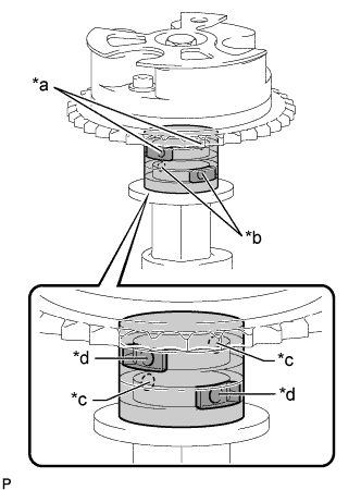
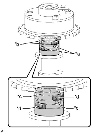
Text in Illustration *a Retard Side Path *b Advance Side Path *c Open *d Close 
Rubber Piece 
Vinyl Tape Cover the 4 oil paths of the cam journal with vinyl tape as shown in the illustration.
Tech Tips
1 retard side path and 1 advance side path are provided in the groove of the camshaft. Plug one of the paths with a rubber piece.
-
Break through the tape over the advance side path, and then break through the tape over the retard side path on the opposite side from the hole over the advance side path as shown in the illustration.
-
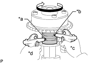
Text in Illustration *a Retard Side Path *b Advance Side Path Apply compressed air at approximately 200 kPa (2.0 kgf/cm2, 28 psi) to the 2 open paths accessible through the holes in the tape.
Note
Cover the paths with a piece of cloth when applying pressure to keep oil from splashing.
-
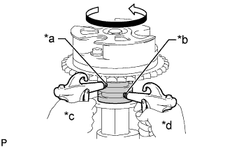
Text in Illustration *a Retard Side Path *b Advance Side Path *c Decompress *d Hold Pressure Check that the camshaft timing gear assembly revolves in the advance direction when reducing the air pressure applied to the retard side path.
OK Gear rotates in the advance direction. Tech Tips
This operation releases the lock pin which holds the timing gear in the most retarded position.
-
When the camshaft timing gear assembly reaches the most advanced position, release the air pressure from the retard side path and advance side path in that order.
Note
-
Do not release the air pressure from the advance side path first. The gear may abruptly shift in the retard direction and break the lock pin.
-
When releasing the air pressure from the advance side path, release it slowly.
-
-
-
Check for smooth rotation.
-
Rotate the camshaft timing gear assembly within its movable range several times, but do not turn it to the most retarded position. Check that the gear rotates smoothly.
CAUTION:
Do not use air pressure to perform the smooth operation check.
-
-
Check the lock in the most retarded position.
-
Confirm that the camshaft timing gear assembly becomes locked at the most retarded position.
-
-
-
REMOVE CAMSHAFT TIMING GEAR ASSEMBLY
-
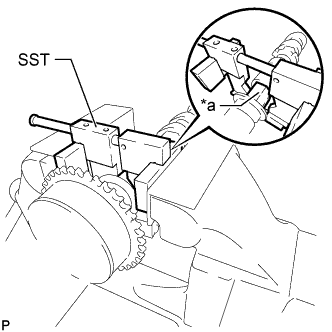
Text in Illustration *a Hexagonal Portion Using SST, grip the hexagonal portion, and then secure the SST and camshaft in a vise as shown in the illustration.
- SST
- 09212-31010
Note
-
Do not damage the camshaft.
-
Never grip areas other than the hexagonal portion, as this may cause damage.
-
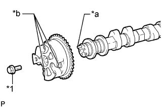
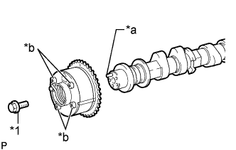
Text in Illustration *1 Flange Bolt *a Straight Pin *b Do Not Remove Remove the flange bolt and camshaft timing gear assembly.
Note
-
Be sure not to remove the other 3 bolts.
-
If planning to reuse the gear, be sure to release the straight pin lock before installing the gear.
-
-
-
INSPECT CAMSHAFT TIMING EXHAUST GEAR ASSEMBLY
-
Check the lock of the camshaft timing exhaust gear assembly.
-
Text in Illustration *a Hexagonal Portion Using SST, grip the hexagonal portion, and then secure the SST and No. 2 camshaft in a vise as shown in the illustration and check that the camshaft timing exhaust gear assembly does not rotate.
- SST
- 09212-31010
Note
-
Do not damage the No. 2 camshaft.
-
Never grip areas other than the hexagonal portion, as this may cause damage.
-
-
Text in Illustration *a Retard Side Path *b Advance Side Path *c Open *d Close Rubber Piece Vinyl Tape Release the lock pin.
-
Clean the No. 2 camshaft journal with non-residue solvent.
-
Cover the 4 oil paths of the cam journal with vinyl tape as shown in the illustration.
Tech Tips
There are 4 oil paths in the grooves of the No. 2 camshaft. Plug 2 paths with pieces of rubber.
-
Break through the tape over the advance side path, and then break through the tape over the retard side path on the opposite side from the hole over the advance side path as shown in the illustration.
-
Text in Illustration *a Retard Side Path *b Advance Side Path Apply compressed air at approximately 200 kPa (2.0 kgf/cm2, 28 psi) to the 2 open paths (the advance side path and retard side path).
Note
Cover the paths with a piece of cloth when applying pressure to keep oil from splashing.
Tech Tips
The lock pin is released in this condition.
-
Text in Illustration *a Retard Side Path *b Advance Side Path *c Decompress *d Hold Pressure Check that the camshaft timing exhaust gear assembly turns in the retard direction when reducing the air pressure applied to the advance side path.
Tech Tips
The lock pin is released and the camshaft timing exhaust gear assembly turns in the retard direction.
-
When the camshaft timing exhaust gear assembly moves to the most retarded position, release the air pressure from the advance side path, and then release the air pressure from the retard side path.
Note
Be sure to release the air pressure from the advance side path first. If the air pressure of the retard side path is released first, the camshaft timing exhaust gear assembly may abruptly shift in the advance direction and break the lock pin or other parts.
-
-
Check for smooth rotation.
-
Turn the camshaft timing exhaust gear assembly within its movable range (21.5 to 23.5°) 2 or 3 times, but do not turn it to the most advanced position. Make sure that the gear turns smoothly.
Note
When the air pressure is released from the advance side path and then from the retard side path, the gear automatically returns to the most advanced position due to the advance assist spring operation, and locks. Gradually release the air pressure from the retard side path before performing the smooth rotation check.
-
-
Check the lock at the most advanced position.
-
Make sure that the camshaft timing exhaust gear assembly locks at the most advanced position.
-
-
-
REMOVE CAMSHAFT TIMING EXHAUST GEAR ASSEMBLY
-
Text in Illustration *a Hexagonal Portion Using SST, grip the hexagonal portion, and then secure the SST and No. 2 camshaft in a vise as shown in the illustration.
- SST
- 09212-31010
Note
-
Do not damage the No. 2 camshaft.
-
Never grip areas other than the hexagonal portion, as this may cause damage.
-
Text in Illustration *1 Flange Bolt *a Straight Pin *b Do Not Remove Remove the flange bolt and camshaft timing exhaust gear assembly.
Note
Be sure not to remove the other 4 bolts.
-
-
REMOVE CYLINDER HEAD SUB-ASSEMBLY
-
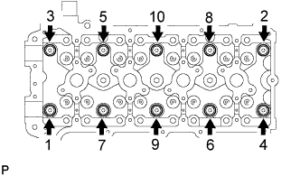
Uniformly loosen the 10 bolts in the sequence shown in the illustration. Remove the 10 cylinder head set bolts and plate washers.
Note
-
Be careful not to drop plate washers into the cylinder head sub-assembly.
-
Head warpage or cracking could result from removing bolts in the incorrect order.
-
-
Remove the cylinder head sub-assembly.
-
-
REMOVE CYLINDER HEAD GASKET
-
REMOVE OIL FILTER ELEMENT
-
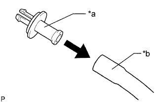
Text in Illustration *a Oil Filter Drain Pipe *b Hose Connect a hose with an inside diameter of 15 mm (0.591 in.) to the oil filter drain pipe.
-
Remove the oil filter drain plug.
-
Remove the O-ring from the oil filter drain plug and install it to an oil filter drain pipe.
-
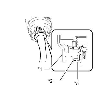
Text in Illustration *1 Oil Filter Cap *2 O-Ring *a Oil Filter Drain Pipe Install the oil filter drain pipe to the oil filter cap and drain the engine oil.
-
Remove the oil filter drain pipe.
-
Apply a light coat of engine oil to a new O-ring and install it to the oil filter drain plug.
-
Install the oil filter drain plug to the oil filter cap.
- Torque:
- 13 N*m { 127 kgf*cm, 9 ft.*lbf }
-
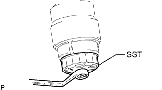
Using SST, remove the oil filter cap.
- SST
- 09228-06501
-
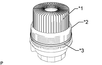
Text in Illustration *1 Oil Filter Element *2 Oil Filter Cap *3 O-Ring Remove the oil filter element and O-ring from the oil filter cap.
-
-
REMOVE OIL FILTER BRACKET SUB-ASSEMBLY
-
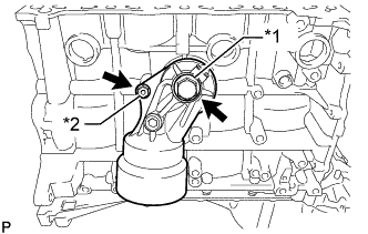
Text in Illustration *1 Union Bolt *2 Nut Remove the union bolt, gasket and O-ring.
-
Remove the nut, oil filter bracket sub-assembly and O-ring.
-
Remove the 2 straight screw plugs and 2 gaskets from the oil filter bracket sub-assembly.
-
-
REMOVE REAR ENGINE OIL SEAL RETAINER
-
Remove the 6 bolts.
-
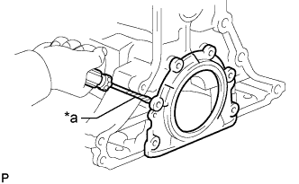
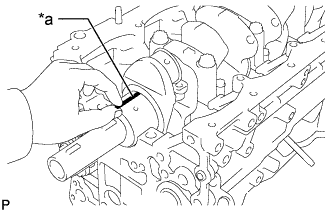
Text in Illustration *a Protective Tape Using a screwdriver with its tip taped, pry out the rear engine oil seal retainer.
Tech Tips
Tape the screwdriver tip before use.
-
-
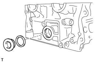
REMOVE REAR CRANKSHAFT OIL SEAL
-
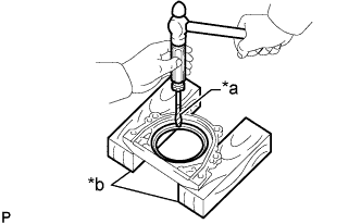
Text in Illustration *a Protective Tape *b Wooden Blocks Place the rear crankshaft oil seal retainer on wooden blocks.
-
Using a screwdriver with its tip taped and a hammer, tap out the rear crankshaft oil seal.
Tech Tips
Tape the screwdriver tip before use.
-
-
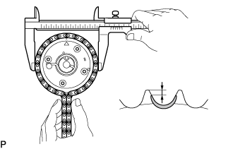
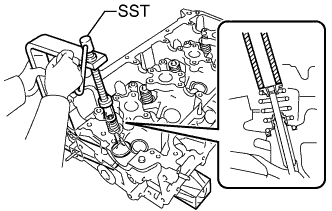
INSPECT CHAIN SUB-ASSEMBLY
-
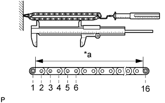
Text in Illustration *a Measuring Area Pull the chain with a force of 147 N (15 kgf, 33.0 lbf) as shown in the illustration.
-
Using a vernier caliper, measure the length of 16 links.
Maximum chain elongation 147.5 mm (5.81 in.) If the elongation is more than the maximum, replace the chain sub-assembly.
Note
Perform the measurement at 3 random places.
Use the average of the measurements.
-
-
INSPECT NO. 1 CHAIN TENSIONER ASSEMBLY
-
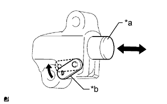
Text in Illustration *a Plunger *b Stopper Plate Move the stopper plate upward to release the lock. Push the plunger and check that it moves smoothly.
-
-
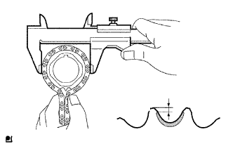
INSPECT CAMSHAFT TIMING GEAR ASSEMBLY
-
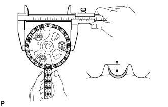
Measure the distance between the most worn out timing gear tip and the beginning of the worn area below the tip.
Minimum distance 1.0 mm (0.0394 in.) Text in Illustration Worn Area If the distance is less than the minimum, replace the camshaft timing gear assembly.
If the worn area is too small or difficult to distinguish from a normal area, perform steps (b) and (c) below.
-
Wrap the chain around the timing gear.
-
Using a vernier caliper, measure the sprocket diameter with the chain.
Minimum sprocket diameter (with chain) 113.8 mm (4.48 in.) Tech Tips
The vernier caliper must contact the chain rollers for the measurement.
If the diameter is less than the minimum, replace the chain sub-assembly and camshaft timing gear assembly.
-
-
INSPECT CAMSHAFT TIMING EXHAUST GEAR ASSEMBLY
-
Measure the distance between the most worn out timing gear tip and the beginning of the worn area below the tip.
Minimum distance 1.0 mm (0.0394 in.) Text in Illustration Worn Area If the distance is less than the minimum, replace the camshaft timing exhaust gear assembly.
If the worn area is too small or difficult to distinguish from a normal area, perform steps (b) and (c) below.
-
Wrap the chain around the timing gear.
-
Using a vernier caliper, measure the sprocket diameter with the chain.
Minimum sprocket diameter (with chain) 113.8 mm (4.48 in.) Tech Tips
The vernier caliper must contact the chain rollers for the measurement.
If the diameter is less than the minimum, replace the chain sub-assembly and camshaft timing exhaust gear assembly.
-
-
INSPECT CRANKSHAFT TIMING GEAR OR SPROCKET
-
Measure the distance between the most worn out sprocket tip and the beginning of the worn area below the tip.
Minimum distance 1.0 mm (0.0394 in.) Text in Illustration Worn Area If the distance is less than the minimum, replace the crankshaft timing gear or sprocket.
If the worn area is too small or difficult to distinguish from a normal area, perform steps (b) and (c) below.
-
Wrap the chain around the drive sprocket.
-
Using a vernier caliper, measure the sprocket diameter with the chain sub-assembly.
Minimum sprocket diameter (with chain) 59.4 mm (2.34 in.) Tech Tips
The vernier caliper must contact the chain rollers for the measurement.
If the diameter is less than the minimum, replace the chain sub-assembly and crankshaft timing gear or sprocket.
-
-
INSPECT CHAIN TENSIONER SLIPPER
-
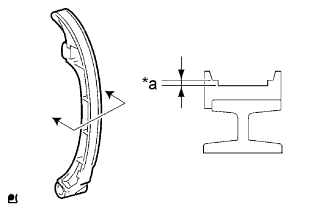
Text in Illustration *a Wear Using a vernier caliper, measure the tensioner slipper wear.
Maximum wear 2.0 mm (0.0787 in.) If the wear is more than the maximum, replace the chain tensioner slipper
-
-
INSPECT NO. 1 CHAIN VIBRATION DAMPER
-
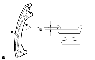
Text in Illustration *a Wear Using a vernier caliper, measure the vibration damper wear.
Maximum wear 2.0 mm (0.0787 in.) If the wear is more than the maximum, replace the No. 1 chain vibration damper.
-
-
INSPECT TIMING CHAIN GUIDE
-
Using a vernier caliper, measure the chain guide wear.
Maximum wear 0.5 mm (0.0197 in.) Text in Illustration Wear If the wear is more than the maximum, replace the timing chain guide.
-
-
INSPECT CYLINDER HEAD SET BOLT
-
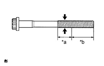
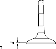
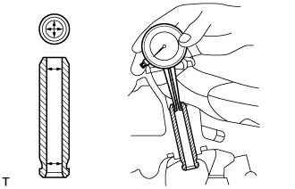
Text in Illustration *a Measuring area *b Distance Using a vernier caliper, measure the diameter of the most elongated threads in the measuring area.
Standard outside diameter 10.76 to 10.97 mm (0.424 to 0.432 in.) Minimum outside diameter 10.40 mm (0.409 in.) Distance 30 mm (1.18 in.) If a visual check reveals no excessively thin areas, check the center of the measuring area (see illustration) and find the area that has the smallest diameter.
If the diameter is less than the minimum, replace the cylinder head set bolt.
-
-
INSPECT VALVE LASH ADJUSTER ASSEMBLY
Note
-
Keep the valve lash adjuster assembly free from dirt and foreign objects.
-
Only use clean engine oil.
-
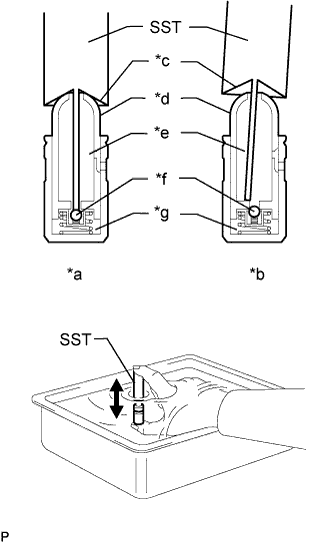
Text in Illustration *a CORRECT *b INCORRECT *c Tapered Part *d Plunger *e Low Pressure Chamber *f Check Ball *g High Pressure Chamber Place the valve lash adjuster assembly into a container full of new engine oil.
-
Insert the tip of SST into the valve lash adjuster assembly plunger and use the tip to press down on the check ball inside the plunger.
- SST
- 09276-71010
-
Squeeze SST and the valve lash adjuster assembly together to move the plunger up and down 5 to 6 times.
-
Check the movement of the plunger and bleed air.
OK Plunger moves up and down. Note
When bleeding high-pressure air from the compression chamber, make sure that the tip of SST is actually pressing the check ball as shown in the illustration. If the check ball is not pressed, air will not bleed.
-
After bleeding the air, remove SST. Then try to quickly and firmly press the plunger with your fingers.
OK Plunger can be pressed 3 times. If the plunger can still be compressed after pressing it 3 times, replace the valve lash adjuster assembly with a new one.
-
-
REMOVE INTAKE VALVE
-

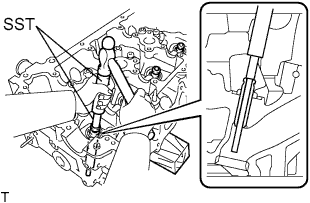
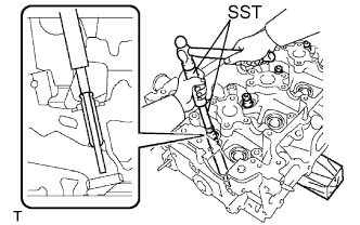
Using SST and wooden blocks, compress the inner compression spring and remove the valve spring retainer locks.
- SST
- 09202-70020
- 09202-00021
-
Remove the valve spring retainer, inner compression spring, and intake valve.
Tech Tips
Arrange the removed parts in the correct order.
-
-
REMOVE EXHAUST VALVE
-
Using SST and wooden blocks, compress the inner compression spring and remove the valve spring retainer locks.
- SST
- 09202-70020
- 09202-00021
-
Remove the valve spring retainer, inner compression spring, and exhaust valve.
Tech Tips
Arrange the removed parts in the correct order.
-
-
REMOVE VALVE STEM OIL SEAL
-
Using needle-nose pliers, remove the valve stem oil seals.
Tech Tips
Arrange the removed parts in the correct order.
-
-
REMOVE VALVE SPRING SEAT
-
Remove the valve spring seats from the cylinder head.
Tech Tips
Arrange the removed parts in the correct order.
-
-
REMOVE OIL CONTROL VALVE FILTER
-

Using an 8 mm hexagon wrench, remove the screw plug.
-
Remove the oil control valve filter and gasket.
-
-
REMOVE NO. 1 HEAD STRAIGHT SCREW PLUG
Note
If coolant leaks from a No. 1 head straight screw plug or a plug is corroded, replace it.
-
Using a 10 mm hexagon wrench, remove the 3 No. 1 head straight screw plugs and 3 gaskets.
-
-
REMOVE NO. 2 HEAD STRAIGHT SCREW PLUG
Note
If coolant leaks from the No. 2 head straight screw plug or the plug is corroded, replace it.
-
Using a 19 mm hexagon wrench, remove the No. 2 head straight screw plug and gasket.
-
-
INSPECT CYLINDER HEAD SUB-ASSEMBLY
-
Text in Illustration *a Cylinder Block Side *b Intake Manifold Side *c Exhaust Manifold Side Using a precision straightedge and feeler gauge, measure the warpage of the contact surface of the cylinder block and manifolds.
Maximum warpage 0.05 mm (0.00197 in.) If the warpage is more than the maximum, replace the cylinder head sub-assembly.
-
Using a dye penetrant, check the intake ports, exhaust ports and cylinder surface for cracks.
If cracked, replace the cylinder head sub-assembly.
-
-
INSPECT INTAKE VALVE SEATS
-
Apply a light coat of Prussian blue to the valve face.
-
Lightly press the valve face against the valve seat.
Tech Tips
Do not rotate the valve while pressing the valve against the valve seat.
-
Check the valve face and valve seat by using the following procedure.
-
If Prussian blue appears around the entire valve face, the valve face is concentric. If not, replace the valve.
-
If Prussian blue appears around the entire valve seat, the guide and valve face are concentric. If not, resurface the valve seat.
-
Text in Illustration *a Width Check that the valve seat contacts in the middle of the valve face with the width between 1.0 and 1.4 mm (0.0394 and 0.0551 in.).
-
-
-
INSPECT EXHAUST VALVE SEATS
-
Apply a light coat of Prussian blue to the valve face.
-
Lightly press the valve face against the valve seat.
Tech Tips
Do not rotate the valve while pressing the valve against the valve seat.
-
Check the valve face and valve seat by using the following procedure.
-
If Prussian blue appears around the entire valve face, the valve face is concentric. If not, replace the valve.
-
If Prussian blue appears around the entire valve seat, the guide and valve face are concentric. If not, resurface the valve seat.
-
Text in Illustration *a Width Check that the valve seat contacts in the middle of the valve face with the width between 1.0 and 1.4 mm (0.0394 and 0.0551 in.).
-
-
-
REPAIR INTAKE VALVE SEAT
Note
-
Repair the seat while checking the seating position.
-
Keep the lip free of foreign matter.
-
Take off the cutter gradually to make the intake valve seat smooth.
-
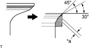
Text in Illustration *a Width If the seating is too high on the valve face, use 30° and 45° cutters to correct the seat.
-
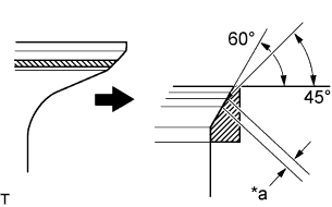
Text in Illustration *a Width If the seating is too low on the valve face, use 60° and 45° cutters to correct the seat.
-
Hand-lap the valve and valve seat with an abrasive compound.
-
Check the valve seating position.
Standard width 1.0 to 1.4 mm (0.0394 to 0.0551 in.)
-
-
REPAIR EXHAUST VALVE SEAT
Note
-
Repair the seat while checking the seating position.
-
Keep the lip free of foreign matter.
-
Take off the cutter gradually to make the exhaust valve seat smooth.
-
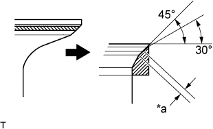
Text in Illustration *a Width If the seating is too high on the valve face, use 30° and 45° cutters to correct the seat.
-

Text in Illustration *a Width If the seating is too low on the valve face, use 60° and 45° cutters to correct the seat.
-
Hand-lap the valve and valve seat with an abrasive compound.
-
Check the valve seating position.
Standard width 1.0 to 1.4 mm (0.0394 to 0.0551 in.)
-
-
INSPECT CAMSHAFT
-
Check the camshaft for runout.
-
Place the camshaft on V-blocks.
-
Using a dial indicator, measure the circle runout at the center journal.
Maximum circle runout 0.03 mm (0.00118 in.) If the circle runout is more than the maximum, replace the camshaft.
-
-
Using a micrometer, measure the cam lobe height.
Standard cam lobe height 42.855 to 42.955 mm (1.687 to 1.691 in.) Minimum cam lobe height 42.855 mm (1.687 in.) If the cam lobe height is less than the minimum, replace the camshaft.
-
Using a micrometer, measure the journal diameter.
Standard Journal Diameter Item Specified Condition No. 1 journal 35.949 to 35.965 mm (1.415 to 1.416 in.) Other journal 26.959 to 26.975 mm (1.061 to 1.062 in.) If the journal diameter is not as specified, check the oil clearance.
-
-
INSPECT NO. 2 CAMSHAFT
-
Check the No. 2 camshaft for runout.
-
Place the No. 2 camshaft on V-blocks.
-
Using a dial indicator, measure the circle runout at the center journal.
Maximum circle runout 0.03 mm (0.00118 in.) If the circle runout is more than the maximum, replace the No. 2 camshaft.
-
-
Using a micrometer, measure the cam lobe height.
Standard cam lobe height 42.854 to 42.954 mm (1.687 to 1.691 in.) Minimum cam lobe height 42.854 mm (1.687 in.) If the cam lobe height is less than the minimum, replace the No. 2 camshaft.
-
Using a micrometer, measure the journal diameter.
Standard Journal Diameter Item Specified Condition No. 1 journal 35.949 to 35.965 mm (1.415 to 1.416 in.) Other journal 26.959 to 26.975 mm (1.061 to 1.062 in.) If the journal diameter is not as specified, check the oil clearance.
-
-
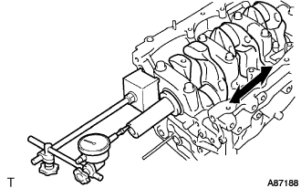
INSPECT CAMSHAFT THRUST CLEARANCE
-
Install the camshafts Click here.
-
Using a dial indicator, measure the thrust clearance while moving the camshaft back and forth.
Standard thrust clearance 0.10 to 0.24 mm (0.00394 to 0.00945 in.) Maximum thrust clearance 0.26 mm (0.0102 in.) If the thrust clearance is more than the maximum, replace the cylinder head sub-assembly. If the thrust surface is damaged, replace the camshaft.
-
-
INSPECT CAMSHAFT OIL CLEARANCE
-
Clean the camshaft bearing caps and camshaft journals.
-
Place the camshafts on the cylinder head sub-assembly.
-
Text in Illustration *a Plastigage Lay a strip of Plastigage across each of the camshaft journals.
-
Install the camshaft bearing caps Click here.
Note
Do not turn the camshaft.
-
Remove the camshaft bearing caps Click here.
-
Text in Illustration *a Plastigage Measure the Plastigage at its widest point.
Standard Journal Diameter Item Specified Condition No. 1 journal 0.035 to 0.072 mm (0.00138 to 0.00283 in.) Other journal 0.025 to 0.062 mm (0.000984 to 0.00244 in.) Maximum oil clearance 0.08 mm (0.00315 in.) If the oil clearance is more than the maximum, replace the camshaft. If necessary, replace the cylinder head sub-assembly.
-
Completely remove the Plastigage.
-
-
INSPECT INNER COMPRESSION SPRING
-

Using a vernier caliper, measure the free length of the inner compression spring.
Standard free length 52.13 mm (2.05 in.) If the free length is not as specified, replace the inner compression spring.
-
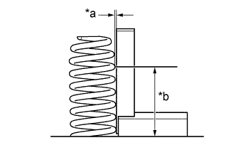
Text in Illustration *a Deviation *b 35 mm (1.38 in.) Using a steel square, measure the deviation of the inner compression spring.
Maximum deviation 1.3 mm (0.0512 in.) Maximum angle 2° If the deviation is more than the maximum, replace the inner compression spring.
-
-
INSPECT INTAKE VALVE
-
Using a vernier caliper, measure the overall length of the intake valve.
Standard overall length 106.56 to 106.96 mm (4.20 to 4.21 in.) Minimum overall length 106.46 mm (4.19 in.) If the overall length is less than the minimum, replace the intake valve.
-
Using a micrometer, measure the diameter of the valve stem.
Standard valve stem diameter 5.470 to 5.485 mm (0.215 to 0.216 in.) -
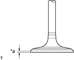
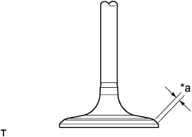
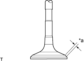
Text in Illustration *a Margin Thickness Using a vernier caliper, measure the valve head margin thickness.
Standard margin thickness 1.05 to 1.45 mm (0.0413 to 0.0571 in.) Minimum margin thickness 0.50 mm (0.0197 in.) If the margin thickness is less than the minimum, replace the intake valve.
-
-
INSPECT EXHAUST VALVE
-
Using a vernier caliper, measure the overall length of the exhaust valve.
Standard overall length 107.04 to 107.44 mm (4.214 to 4.230 in.) Minimum overall length 106.94 mm (4.210 in.) If the overall length is less than the minimum, replace the exhaust valve.
-
Using a micrometer, measure the diameter of the valve stem.
Standard valve stem diameter 5.465 to 5.480 mm (0.215 to 0.216 in.) -
Text in Illustration *a Margin Thickness Using a vernier caliper, measure the valve head margin thickness.
Standard margin thickness 1.2 to 1.6 mm (0.0472 to 0.0630 in.) Minimum margin thickness 0.50 mm (0.0197 in.) If the margin thickness is less than the minimum, replace the exhaust valve.
-
-
INSPECT VALVE GUIDE BUSH OIL CLEARANCE
-
Using a caliper gauge, measure the inside diameter of the valve guide bush.
Standard bush inside diameter 5.51 to 5.53 mm (0.217 to 0.218 in.) -
Subtract the valve stem diameter measurement from the valve guide bush inside diameter measurement.
Standard Oil Clearance Item Specified Condition Intake 0.025 to 0.060 mm (0.000984 to 0.00236 in.) Exhaust 0.030 to 0.065 mm (0.00118 to 0.00256 in.) Maximum Oil Clearance Item Specified Condition Intake 0.08 mm (0.00315 in.) Exhaust 0.10 mm (0.00397 in.) If the clearance is more than the maximum, replace the intake valve and intake valve guide bush (See disassembly, step 72 and reassembly, step 16).
If the clearance is more than the maximum, replace the exhaust valve and exhaust valve guide bush (See disassembly, step 73 and reassembly, step 17).
-
-
REMOVE INTAKE VALVE GUIDE BUSH
-
Heat the cylinder head sub-assembly to 80 to 100°C (176 to 212°F)
-
Place the cylinder head sub-assembly on wooden blocks.
-
Using SST and a hammer, tap out the intake valve guide bush.
- SST
- 09201-01055
- 09950-70010 ( 09951-07100 )
-
-
REMOVE EXHAUST VALVE GUIDE BUSH
-
Heat the cylinder head sub-assembly to 80 to 100°C (176 to 212 °F).
-
Place the cylinder head sub-assembly on wooden blocks.
-
Using SST and a hammer, tap out the exhaust valve guide bush.
- SST
- 09201-01055
- 09950-70010 ( 09951-07100 )
-
-
INSPECT CONNECTING ROD THRUST CLEARANCE
-
Using a dial indicator, measure the thrust clearance while moving the connecting rod back and forth.
Standard thrust clearance 0.15 to 0.35 mm (0.00591 to 0.0138 in.) Maximum thrust clearance 0.40 mm (0.0157 in.) If the thrust clearance is more than the maximum, replace the connecting rod assembly. If necessary, replace the crankshaft.
-
-
INSPECT CONNECTING ROD OIL CLEARANCE
-
Check that the matchmarks on the connecting rod and cap are aligned to ensure the correct reassembly.
Tech Tips
The matchmarks on the connecting rods and caps are for ensuring the correct reassembly.
-
Remove the 2 connecting rod cap bolts.
-
Using the 2 removed connecting rod cap bolts, remove the connecting rod cap and lower connecting rod bearing by wiggling the connecting rod cap right and left.
Tech Tips
Keep the lower connecting rod bearing inserted to the connecting rod cap.
-
Clean the crank pin and lower connecting rod bearing.
-
Check the crank pin and lower connecting rod bearing for pitting and scratches.
-
Text in Illustration *a Plastigage Lay a strip of Plastigage on the crank pin.
-
Text in Illustration *a Front Mark Check that the front mark of the connecting rod cap is facing forward.
-
Install the connecting rod cap Click here.
Note
Do not turn the crankshaft.
-
Remove the 2 bolts and connecting rod cap (refer to the steps above).
-
Text in Illustration *a Plastigage *b Mark 4, 5 or 6 Measure the Plastigage at its widest point.
Standard oil clearance 0.033 to 0.060 mm (0.00130 to 0.00236 in.) Maximum oil clearance 0.060 mm (0.00236 in.) If the oil clearance is more than the maximum, replace the connecting rod bearings. If necessary, replace the crankshaft.
If replacing a bearing, replace it with one that has the same number as its respective connecting rod cap. Each bearing's standard thickness is indicated by a mark 4, 5 or 6 on its surface.
Standard crankshaft pin diameter 52.989 to 53.002 mm (2.086 to 2.087 in.) Standard Connecting Rod Diameter Item Specified Condition Mark 4 56.000 to 56.006 mm (2.20472 to 2.20496 in.) Mark 5 56.007 to 56.012 mm (2.20500 to 2.20519 in.) Mark 6 56.013 to 56.018 mm (2.20523 to 2.20543 in.) Standard Bearing Center Wall Thickness Item Specified Condition Mark 4 1.487 to 1.490 mm (0.0584 to 0.0586 in.) Mark 5 1.491 to 1.493 mm (0.0586 to 0.0587 in.) Mark 6 1.494 to 1.499 mm (0.0589 to 0.0590 in.) -
Completely remove the Plastigage.
-
Perform the inspection above for each crank pin.
-
-
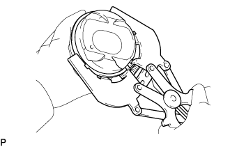
REMOVE PISTON SUB-ASSEMBLY WITH CONNECTING ROD
-
Text in Illustration *a Ridge Reamer Using a ridge reamer, remove all the carbon from the top of the cylinder.
-
Push the piston, connecting rod assembly and upper connecting rod bearing through the top of the cylinder block.
Tech Tips
-
Keep the upper connecting rod bearing, connecting rod and cap together.
-
Arrange the piston and connecting rod assemblies in the correct order.
-
-
-
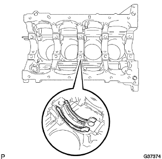
REMOVE CONNECTING ROD BEARING
-
Remove the connecting rod bearings from the connecting rods and connecting rod caps.
Tech Tips
Arrange the removed parts in the correct order.
-
-
INSPECT CRANKSHAFT THRUST CLEARANCE
-
Using a dial indicator, measure the thrust clearance while prying the crankshaft back and forth with a screwdriver.
Standard thrust clearance 0.02 to 0.22 mm (0.000787 to 0.00866 in.) Maximum thrust clearance 0.30 mm (0.0118 in.) If the thrust clearance is more than the maximum, replace the thrust washers as a set. If necessary, replace the crankshaft.
Thrust washer thickness 2.440 to 2.490 mm (0.0961 to 0.0980 in.)
-
-
REMOVE CRANKSHAFT
-
Uniformly loosen the 10 bearing cap bolts in several steps in the sequence shown in the illustration.
-
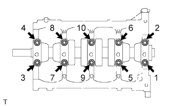
Remove the 10 bearing cap bolts, 5 bearing caps, 5 lower crankshaft bearings and 2 lower crankshaft thrust washers.
Tech Tips
-
Keep the lower crankshaft bearings and crankshaft bearing caps together.
-
Arrange the thrust washers in the correct order.
-
-
Lift out the crankshaft to remove it.
-
Remove the upper thrust washers from the cylinder block.
Tech Tips
Arrange the crankshaft bearing caps, crankshaft bearings and thrust washers in the correct order.
-
-
REMOVE CRANKSHAFT BEARING
-
Remove the crankshaft bearings from the cylinder block and crankshaft bearing caps.
Tech Tips
Arrange the removed parts in the correct order.
-
-
REMOVE PISTON RING SET
-
Using a piston ring expander, remove the 2 compression rings.
-
Remove the oil ring expander and 2 oil ring side rails by hand.
Tech Tips
Arrange the removed parts in the correct order.
-
-
REMOVE CYLINDER BLOCK WATER DRAIN COCK SUB-ASSEMBLY
-
Remove the cylinder block water drain cock sub-assembly from the cylinder block.
-
Remove the water drain cock plug from the cylinder block water drain cock sub-assembly.
-
-
REMOVE PISTON WITH PIN SUB-ASSEMBLY
-
Check the fitting condition between the piston and piston pin.
-
Try to move the piston back and forth on the piston pin.
If any movement is felt, replace the piston and pin as a set.
-
-
Disconnect the connecting rod from the piston.
-
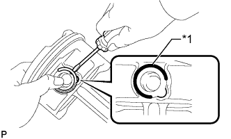
Text in Illustration *1 Snap Ring Using a screwdriver, pry off the 2 snap rings from the piston.
-
Gradually heat the piston to approximately 80 to 90°C (176 to 194°F).
-
Using a brass bar and plastic-faced hammer, lightly tap out the piston pin and remove the connecting rod.
Tech Tips
-
The piston and pin are a matched set.
-
Arrange the pistons, piston pins, piston rings, connecting rods and connecting rod bearings in the correct order.
-
-
-
-
CLEAN PISTON WITH PIN SUB-ASSEMBLY
-
Using a gasket scraper, remove the carbon from the piston top.
-
Using a groove cleaning tool or broken ring, clean the piston ring grooves.
-
Using solvent and a brush, thoroughly clean the piston.
Note
Do not use a wire brush.
-
-
REMOVE NO. 1 OIL NOZZLE SUB-ASSEMBLY
-

Using a 5 mm hexagon wrench, remove the 4 No. 1 oil nozzle sub-assemblies.
-
-
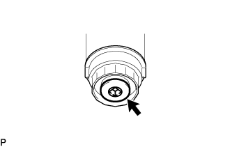
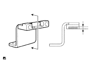
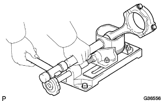
INSPECT NO. 1 OIL NOZZLE SUB-ASSEMBLY
-
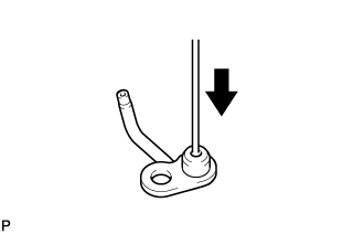
Push the check valve with a pin to check if it is stuck.
Text in Illustration 
Push If the check valve is stuck, replace the No. 1 oil nozzle sub-assembly.
-
Push the check valve with a pin to check if it moves smoothly.
If the check valve does not move smoothly, clean or replace the No. 1 oil nozzle sub-assembly.
-
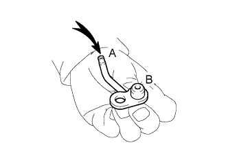
Blow air into A. Check that air does not leak from B.
Text in Illustration Air If air leaks, clean or replace the No. 1 oil nozzle sub-assembly.
-
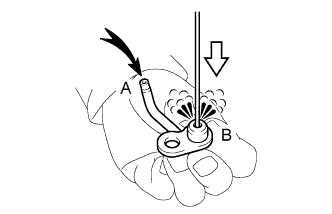
Push the check valve while blowing air into A. Check that air passes through B.
Text in Illustration Air 
Push If air does not pass through B, clean or replace the No. 1 oil nozzle sub-assembly.
-
-
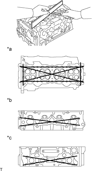
INSPECT CYLINDER BLOCK FOR WARPAGE
-
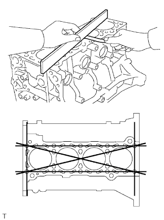
Using a precision straightedge and feeler gauge, measure the warpage of the contact surface of the cylinder head gasket.
Maximum warpage 0.05 mm (0.00197 in.) If the warpage is more than the maximum, replace the cylinder block.
-
Visually check the cylinder for vertical scratches.
If deep scratches are present, rebore all 4 cylinders. If necessary, replace the cylinder block.
-
-
INSPECT CYLINDER BORE
-
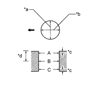
Text in Illustration *a Thrust Direction *b Axial Direction *c 10 mm (0.394 in.) *d 70 mm (2.75 in.) Front Using a cylinder gauge, measure the cylinder bore diameter at position A, B and C in the thrust and axial directions.
Reference value (new parts) 85.990 to 86.003 mm (3.3854 to 3.3859 in.) Maximum diameter 86.190 mm (3.3933 in.) -

Text in Illustration *a Ridge Reamer Inspect the cylinder ridge.
If the wear is less than 0.2 mm (0.00787 in.), using a ridge reamer, grind the top of the cylinder.
-
-
CLEAN CYLINDER BLOCK
-
Using a gasket scraper, remove all the gasket material from the top surface of the cylinder block.
-
Using a soft brush and solvent, thoroughly clean the cylinder block.
-
-
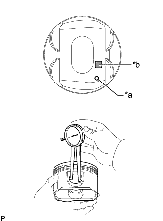
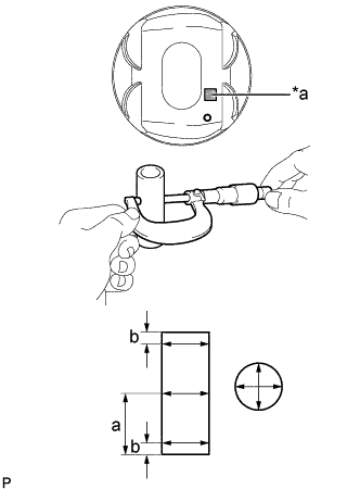
INSPECT PISTON DIAMETER
-
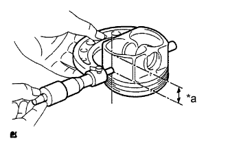
Text in Illustration *a Distance Using a micrometer, measure the piston diameter at right angles to the piston center line where the distance from the piston end is as specified.
Distance 11.6 mm (0.457 in.) Reference value (new parts) 85.977 to 85.987 mm (3.3849 to 3.3853 in.)
-
-
INSPECT PISTON OIL CLEARANCE
-
Measure the cylinder bore diameter in the thrust direction (See step 88).
-
Subtract the piston diameter measurement from the cylinder bore diameter measurement.
Reference value (new parts) 0.003 to 0.024 mm (0.000118 to 0.000945 in.) If the oil clearance is more than the maximum, replace all the pistons. If necessary, replace the cylinder block.
-
-
INSPECT RING GROOVE CLEARANCE
-
Using a feeler gauge, measure the clearance between a new piston ring and the wall of the ring groove.
Standard Ring Groove Clearance Item Specified Condition No. 1 compression ring 0.020 to 0.070 mm (0.000787 to 0.00276 in.) No. 2 compression ring 0.020 to 0.060 mm (0.000787 to 0.00236 in.) Oil ring 0.060 to 0.120 mm (0.00236 to 0.00472 in.) If the groove clearance is not as specified, replace the piston with pin.
-
-
INSPECT PISTON RING END GAP
-
Insert the piston ring into the cylinder bore.
-
Using a piston, push the piston ring a little beyond the bottom of the ring travel, 110 mm (4.33 in.) from the top of the cylinder block.
-
Using a feeler gauge, measure the end gap.
Standard End Gap Item Specified Condition No. 1 compression ring 0.27 to 0.32 mm (0.0106 to 0.0126 in.) No. 2 compression ring 0.45 to 0.57 mm (0.0177 to 0.0224 in.) Oil ring 0.10 to 0.35 mm (0.00394 to 0.0138 in.) Maximum End Gap Item Specified Condition No. 1 compression ring 0.90 mm (0.0354 in.) No. 2 compression ring 1.36 mm (0.0535 in.) Oil ring 0.75 mm (0.0295 in.) If the end gap is more than the maximum, replace the piston ring. If the end gap is more than the maximum even with a new piston ring, replace the cylinder block.
-
-
INSPECT PISTON PIN OIL CLEARANCE
Tech Tips
There is only 1 type of supply part for piston with pin sub-assembly.
-
Text in Illustration *a Front Mark *b Piston Pin Hole Inside Diameter Mark Using a caliper gauge, measure the inside diameter of the piston pin hole.
Standard Piston Pin Hole Inside Diameter Item Specified Condition A 22.001 to 22.004 mm (0.86618 to 0.86630 in.) B 22.005 to 22.007 mm (0.86634 to 0.86642 in.) C 22.008 to 22.010 mm (0.86645 to 0.86653 in.) -
Text in Illustration *a Piston Pin Hole Inside Diameter Mark Using a micrometer, measure the piston pin diameter.
Measurement Position Measurement Position Piston Pin Position a 28 mm (1.10 in.) b 5.0 mm (0.197 in.) Standard Piston Pin Diameter Item Specified Condition A 21.997 to 22.000 mm (0.86602 to 0.86614 in.) B 22.001 to 22.003 mm (0.86618 to 0.86626 in.) C 22.004 to 22.006 mm (0.86630 to 0.86638 in.) -
Subtract the piston pin diameter measurement from the piston pin hole diameter measurement.
Standard oil clearance 0.001 to 0.007 mm (0.0000394 to 0.000276 in.) Maximum oil clearance 0.010 mm (0.000394 in.) If the oil clearance is more than the maximum, replace the piston and piston pin as a set.
-
Text in Illustration *a Connecting Rod Bush Inside Diameter Mark *b Front Mark Using a caliper gauge, measure the inside diameter of the connecting rod bush.
Standard Bush Inside Diameter Item Specified Condition A 22.005 to 22.008 mm (0.86634 to 0.86645 in.) B 22.009 to 22.011 mm (0.86649 to 0.86657 in.) C 22.012 to 22.014 mm (0.86661 to 0.86669 in.) If the diameter is not as specified, replace the connecting rod small end bush.
-
Subtract the piston pin diameter measurement from the small end bush inside diameter measurement.
Standard oil clearance 0.001 to 0.007 mm (0.0000394 to 0.000276 in.) Maximum oil clearance 0.010 mm (0.000394 in.) If the oil clearance is more than the maximum, replace the connecting rod small end bush. If necessary, replace the connecting rod and piston pin as a set.
-
-
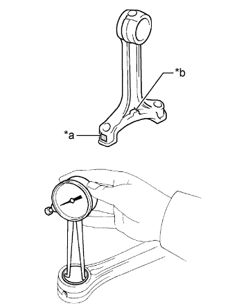
INSPECT CONNECTING ROD SUB-ASSEMBLY
-
Using a rod aligner and feeler gauge, check the connecting rod alignment.
-
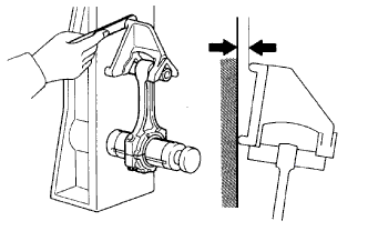
Check for bend.
Maximum bend 0.03 mm (0.00118 in.) per 100 mm (3.94 in.) If the bend is more than the maximum, replace the connecting rod sub-assembly.
-
Check for twist.
Maximum twist 0.15 mm (0.00591 in.) per 100 mm (3.94 in.) If the twist is more than the maximum, replace the connecting rod sub-assembly.
-
-
-
REMOVE CONNECTING ROD SMALL END BUSH
-
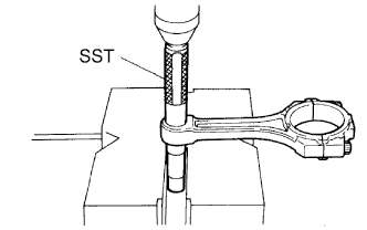
Using SST and a press, press out the connecting rod small end bush.
- SST
- 09222-30010
-
-
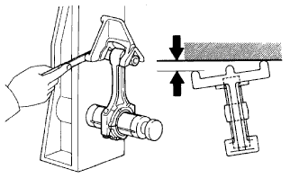
INSPECT CONNECTING ROD BOLT
-
Text in Illustration *a Tension Portion Using a vernier caliper, measure the tension portion diameter of the bolt.
Standard diameter 7.2 to 7.3 mm (0.283 to 0.287 in.) Minimum diameter 7.0 mm (0.276 in.) If the diameter is less than the minimum, replace the connecting rod bolt.
-
-
INSPECT CRANKSHAFT
-
Inspect the circle runout.
-
Place the crankshaft on V-blocks.
-
Using a dial indicator, measure the circle runout at the center journal.
Maximum circle runout 0.03 mm (0.00118 in.) If the circle runout is more than the maximum, replace the crankshaft.
-
-
Inspect the main journals.
-
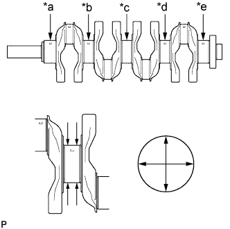
Text in Illustration *a No. 1 *b No. 2 *c No. 3 *d No. 4 *e No. 5 Using a micrometer, measure the diameter of each main journal.
Standard Journal Diameter Item Specified Condition No. 3 journal 59.981 to 59.994 mm (2.361 to 2.362 in.) Except No. 3 journal 59.987 to 60.000 mm (2.3617 to 2.3622 in.) If the diameter is not as specified, check the oil clearance. If necessary, replace the crankshaft.
-
Check each main journal for taper and out-of- round as shown in the illustration.
Maximum taper and out-of-round 0.005 mm (0.000197 in.) If the taper and out-of-round is more than the maximum, replace the crankshaft.
-
-
Inspect the crank pins.
-
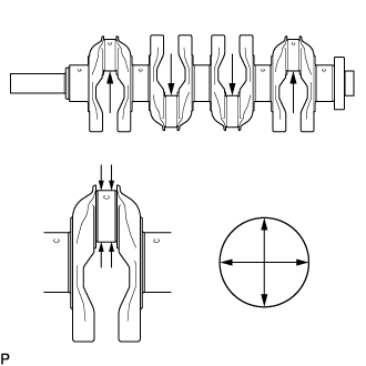
Using a micrometer, measure the diameter of each crank pin.
Standard diameter 52.989 to 53.002 mm (2.086 to 2.087 in.) If the diameter is not as specified, check the oil clearance. If necessary, replace the crankshaft.
-
Check each crank pin for taper and out-of-round as shown in the illustration.
Maximum taper and out-of-round 0.003 mm (0.000118 in.) If the taper and out-of-round is more than the maximum, replace the crankshaft.
-
-
-
INSPECT CRANKSHAFT OIL CLEARANCE
Tech Tips
-
Keep the lower crankshaft bearings and crankshaft bearing caps together.
-
Arrange the thrust washers in the correct order.
-
Keep the upper crankshaft bearings and upper thrust washers together with the cylinder block.
-
Clean each main journal and bearing.
-
Check each main journal and bearing for pitting and scratches.
If the journal or bearing is damaged, replace the bearing.
-
Place the crankshaft on the cylinder block.
-
Text in Illustration *a Plastigage Lay a strip of Plastigage across each journal.
-
Install the 5 crankshaft bearing caps with the 10 bolts Click here.
Note
Do not turn the crankshaft.
-
Remove the 10 bolts and 5 crankshaft bearing caps (refer to the steps above).
-
Measure the Plastigage at its widest point.
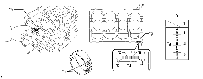
Text in Illustration *a Plastigage *b No. 1 Journal *c No. 2 Journal *d No. 3 Journal *e No. 4 Journal *f No. 5 Journal *g Cylinder Block Journal Code *h Crankshaft Bearing Code *i Bearing Code Chart - - Standard Oil Clearance Item Specified Condition No. 3 journal 0.030 to 0.055 mm (0.00118 to 0.00217 in.) Other journals 0.024 to 0.049 mm (0.000945 to 0.00193 in.) Maximum oil clearance 0.10 mm (0.00394 in.)
-
If the oil clearance is more than the maximum, replace the crankshaft bearing.
-
If replacing the cylinder block, measure the bearing standard clearance.
-
Check the cylinder block journal code and refer to the crankshaft bearing selection chart to select a bearing size.
-
(Example): When the cylinder block journal code is "D", select crankshaft bearing selection code "2" from the crankshaft bearing selection chart.
Cylinder Block Main Journal Bore Diameter Item Specified Condition Mark A 64.004 to 64.006 mm (2.51984 to 2.51992 in.) Mark B 64.007 to 64.008 mm (2.51996 to 2.51999 in.) Mark C 64.009 to 64.010 mm (2.52003 to 2.52007 in.) Mark D 64.011 to 64.012 mm (2.52011 to 2.52015 in.) Mark E 64.013 to 64.014 mm (2.52019 to 2.52023 in.) Mark F 64.015 to 64.016 mm (2.52027 to 2.52031 in.) Mark G 64.017 to 64.018 mm (2.52035 to 2.52039 in.) Mark H 64.019 to 64.020 mm (2.52043 to 2.52047 in.) Mark J 64.021 to 64.022 mm (2.52051 to 2.52055 in.) Standard Bearing Center Wall Thickness Item Specified Condition Mark 1 1.987 to 1.990 mm (0.07823 to 0.07835 in.) Mark 2 1.991 to 1.993 mm (0.07839 to 0.07846 in.) Mark 3 1.994 to 1.996 mm (0.07850 to 0.07858 in.) -
-
Completely remove the Plastigage.
-
-
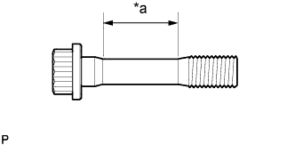
INSPECT CRANKSHAFT BEARING CAP SET BOLT
-
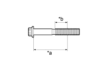
Text in Illustration *a Distance *b Measuring Area Using a vernier caliper, measure the diameter of the most elongated threads in the measuring area.
Distance 64 mm (2.52 in.) Standard diameter 10.76 to 10.97 mm (0.424 to 0.432 in.) Minimum diameter 10.66 mm (0.420 in.) If the diameter is less than the minimum, replace the crankshaft bearing cap set bolt.
-
-
REMOVE RING PIN
Tech Tips
It is not necessary to remove a ring pin unless it is being replaced.
-
REMOVE STRAIGHT PIN
Tech Tips
It is not necessary to remove a straight pin unless it is being replaced.
-
REMOVE STUD BOLT
Tech Tips
If a stud bolt is deformed or its threads are damaged, replace it.
-
REMOVE TIGHT PLUG
Tech Tips
If coolant leaks from a tight plug or a plug is corroded, replace it.