ENGINE UNIT DISASSEMBLY

-
REMOVE OIL FILLER CAP SUB-ASSEMBLY
-
REMOVE CYLINDER HEAD COVER SUB-ASSEMBLY
-
Remove the 9 bolts, nut, cylinder head cover, and gasket.
-
-
REMOVE CAMSHAFT TIMING PULLEY
-
Set the No.1 cylinder to approx. 90° BTDC/compression.
Tech Tips
Set the No.1 cylinder to 90° BTDC/compression to avoid interference with the piston top and valve head.
-
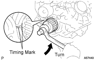
Using the crankshaft pulley bolt, turn the crankshaft 90°counterclockwise, and put the timing mark of the crankshaft timing pulley with the protrusion of the timing belt case.
-
-
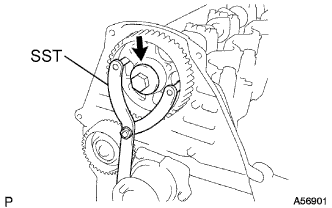
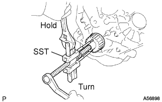
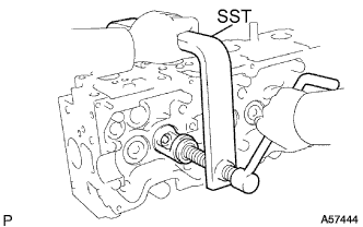
Using SST, loosen the pulley bolt.
- SST
- 09960-10010 ( 09962-01000, 09963-01000 )
-
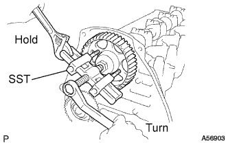
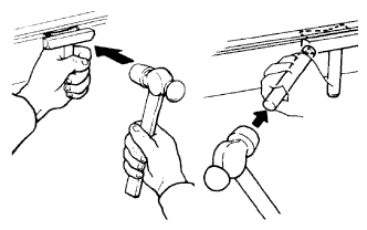
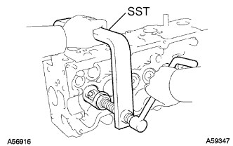
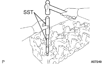
Using SST, separate the timing pulley from the camshaft.
- SST
- 09950-50013 ( 09951-05010, 09952-05010, 09953-05010, 09954-05021 )
-
Remove the pulley bolt and timing pulley.
-
Remove the timing gear woodruff key.
-
-
REMOVE TIMING BELT COVER NO.2
-
Remove the 4 bolts and timing belt cover.
-
-
REMOVE CAMSHAFT OIL SEAL RETAINER
-
Remove the 4 bolts, retainer and gasket.
-
-
REMOVE OIL SEAL RETAINER, NO.2 OIL SEAL
-
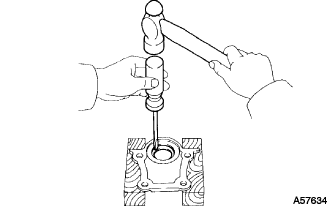
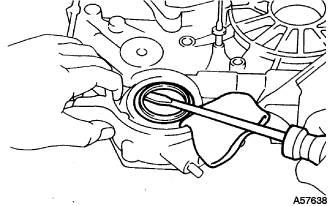
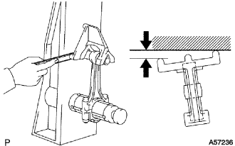
Using a screwdriver and hammer, tap out the oil seal.
Note
Tape the screwdriver tip.
-
-
REMOVE CAMSHAFT
-
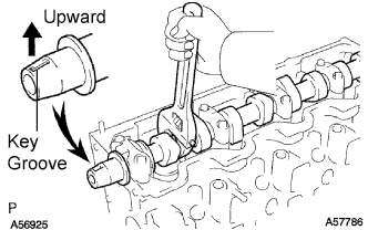
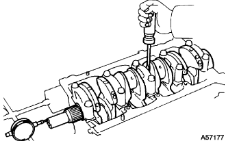
Turn the camshaft with a wrench so that the key groove faces upward.
-
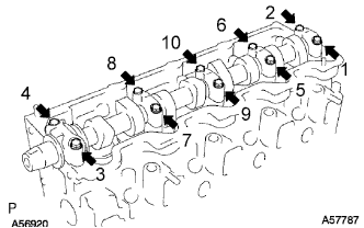
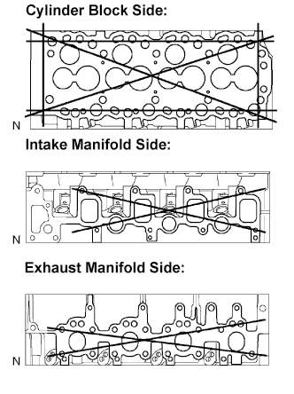
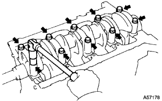
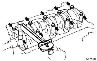
Uniformly loosen and remove the 10 bearing cap bolts, in several steps, in the sequence shown.
-
Remove the 5 bearing caps and camshaft.
-
Remove the 10 bearings from the bearing caps and cylinder head.
Tech Tips
Arrange the bearings in the correct order.
-
-
REMOVE CYLINDER HEAD SUB-ASSEMBLY
-
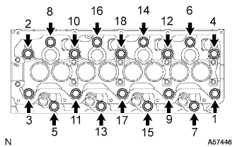
Uniformly loosen and remove the 18 cylinder head bolts, in several steps, in the sequence shown.
Note
Head warpage or cracking could result from removing bolts in an incorrect order.
-
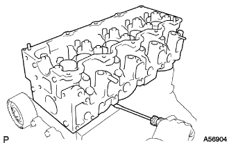
Lift the cylinder head from the dowels on the cylinder block, and place the cylinder head on wooden blocks on a bench.
Note
Do not damage the contact surfaces of the cylinder head and cylinder block.
If the cylinder head is difficult to lift off, pry with a screwdriver between the cylinder head and block.
-
-
REMOVE CYLINDER HEAD GASKET
-
Remove the cylinder gasket from the cylinder head.
-
-
REMOVE TIMING BELT IDLER SUB-ASSEMBLY NO.1
-
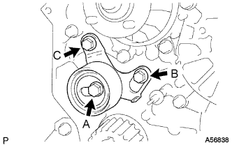
Remove the 2 bolts (A and B).
-
Loosen the bolt (C), and remove the timing belt idler No.1.
-
-
REMOVE TIMING BELT IDLER SUB-ASSEMBLY NO.2
-
Remove the bolt, timing belt idler No.2 and spacer.
-
-
INSPECT TIMING BELT IDLER SUB-ASSEMBLY NO.1
-
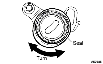
Visually check the seal portion of the timing belt idler No.1 for oil leakage.
If leakage is found, replace the timing belt idler No.1.
-
Check that the timing belt idler No.1 turns smoothly.
If necessary, replace the timing belt idler No.1.
-
-
INSPECT TIMING BELT IDLER SUB-ASSEMBLY NO.2
-
Check that the timing belt idler No.2 turns smoothly.
If necessary, replace the timing belt idler No.2.
-
-
INSPECT IDLER TENSION SPRING
-
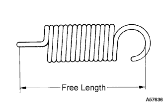
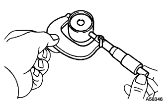
Measure the free length of the tension spring.
Free length 44.4 to 45.4 mm (1.748 to 1.787 in.) If the free length is not as specified, replace the tension spring.
-
Measure the tension of the tension spring at the specified installed length.
Installed tension 53 to 59 N (5.42 to 5.98 kgf, 11.9 to 13.2 lbf) at 52.1 mm (2.051 in.) If the installed tension is not as specified, replace the tension spring.
-
-
REMOVE WATER PUMP ASSEMBLY
-
Remove the 6 bolts, tension spring bracket, water pump and gasket.
-
-
REMOVE CRANKSHAFT TIMING PULLEY
-
If the timing pulley cannot be removed by a screwdriver, remove it with SST.
- SST
- 09950-50013 ( 09951-05010, 09952-05010, 09953-05010, 09953-05020, 09954-05010 )
-
-
REMOVE OIL PAN SUB-ASSEMBLY
-
Remove the 16 bolts and 2 nuts.
-
Insert the blade of a oil pan seal cutter between the oil pan and cylinder block, and cut off applied sealer and remove the oil pan.
Note
-
Do not use a oil pan seal cutter for the timing belt case side and rear oil seal retainer.
-
Do not damage the oil pan flange.
-
-
-
REMOVE OIL STRAINER SUB-ASSEMBLY
-
Remove the 2 bolts, 2 nuts, oil strainer and gasket.
-
-
REMOVE TIMING GEAR CASE SUB-ASSEMBLY
-
Remove the 5 bolts, timing gear case and gasket.
-
-
REMOVE TIMING GEAR CASE OR TIMING CHAIN CASE OIL SEAL
-
Using a screwdriver and hammer, tap out the oil seal.
Note
Tape the screwdriver tip.
-
-
REMOVE ENGINE REAR OIL SEAL RETAINER
-
Remove the 4 bolts, oil seal retainer and gasket.
-
-
REMOVE ENGINE REAR OIL SEAL
-
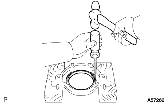
Using a screwdriver and hammer, tap out the oil seal.
Note
Tape the screwdriver tip.
-
-
INSPECT CYLINDER HEAD SET BOLT
-
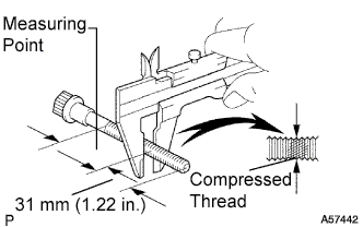
Using vernier calipers, measure the minimum outer diameter of the compressed thread at the measuring point.
Standard outer diameter 11.80 to 12.00 mm (0.4646 to 0.4724 in.) Minimum outer diameter 11.60 mm (0.4567 in.) If the outer diameter is less than the minimum, replace the bolt.
-
-
REMOVE VALVE LIFTER
-
Remove the valve lifter and adjusting shim.
Tech Tips
Arrange the valve lifters and shims in the correct order.
-
-
REMOVE INTAKE VALVE
-
Using SST, compress the valve spring and remove the 2 retainer locks.
- SST
- 09202-70020 ( 09202-00030 )
-
Remove the spring retainer, valve spring, valve and spring seat.
Tech Tips
Arrange the valves, valve springs, spring seats and spring retainers in the correct order.
-
-
REMOVE EXHAUST VALVE
-
Using SST, compress the valve spring and remove the 2 retainer locks.
- SST
- 09202-70020 ( 09202-00030 )
-
Remove the spring retainer, valve spring, valve and spring seat.
Tech Tips
Arrange the valves, valve springs, spring seats and spring retainers in the correct order.
-
-
REMOVE VALVE STEM OIL SEAL
-
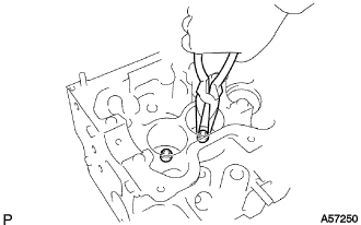
Using needle-nose pliers, remove the oil seal.
-
-
REMOVE COMBUSTION CHAMBER SUB-ASSEMBLY
-
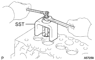
Using SST, remove the 4 combustion chambers (and shims).
- SST
- 09208-48010
Tech Tips
Arrange the combustion chambers (and shims) in the correct order.
-
-
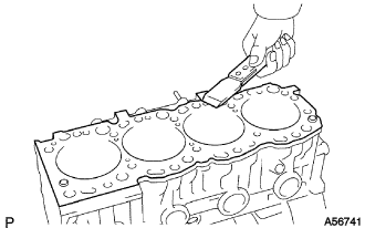
CLEAN CYLINDER HEAD SUB-ASSEMBLY
-
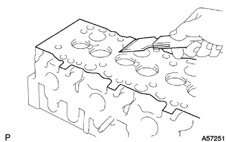
Using a gasket scraper, remove all the gasket material from the cylinder block contact surface.
Note
Do not scratch the cylinder block contact surface.
-
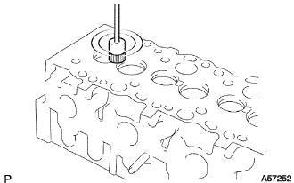
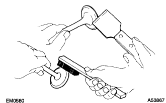
Using a wire brush, remove all the carbon from the combustion chambers.
Note
Do not scratch the cylinder block contact surface.
-
Using a valve guide bushing brush and solvent, clean all the guide bushes.
-
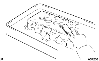
Using a soft brush and solvent, thoroughly clean the cylinder head.
-
-
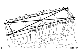
INSPECT CYLINDER HEAD SUB-ASSEMBLY
-
Inspect for warpage.
-
Using a precision straight edge and feeler gauge, measure the surfaces contacting the cylinder block and the manifolds for warpage.
Maximum warpage 0.20 mm (0.0079 in.) If warpage is greater than the maximum, replace the cylinder head.
-
-
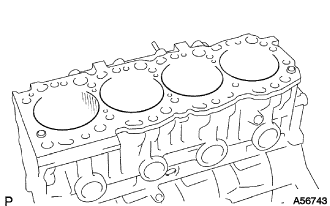
Inspect for cracks.
-

Using a dye penetrant, check the combustion chamber, intake ports, exhaust ports and cylinder block surface for cracks.
If cracked, replace the cylinder head.
-
-
-
CLEAN INTAKE VALVE
-
Using a gasket scraper, chip off any carbon from the valve head.
-
Using a wire brush, thoroughly clean the valve.
-
-
INSPECT INTAKE VALVE
-
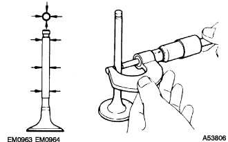
Using a micrometer, measure the diameter of the valve stem.
Valve stem diameter 7.975 to 7.990 mm (0.3140 to 0.3146 in.) -
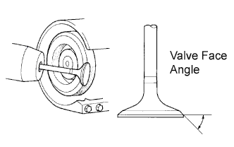
Check the valve face angle.
-
Grind the valve enough to remove pits and carbon.
-
Check that the valve is ground to the correct valve face angle.
Valve face angle 44.5°
-
-
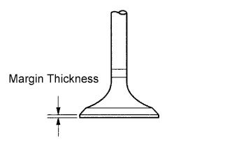
Check the valve head margin thickness.
Standard margin thickness 1.6 mm (0.063 in.) Minimum margin thickness 1.1 mm (0.043 in.) If the margin thickness is less than the minimum, replace the valve.
-
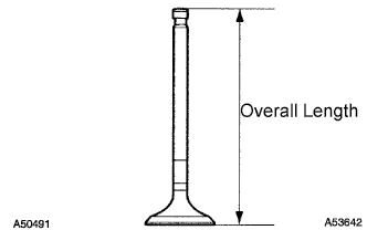
Check the valve overall length.
Standard overall length 104.10 to 104.50 mm (4.0984 to 4.1142 in.) Minimum overall length 103.60 mm (4.0787 in.) If the overall length is less than the minimum, replace the valve.
-
Check the surface of the valve stem tip for wear.
Note
Do not grind off more than minimum.
If the valve stem tip is worn, resurface the tip with a grinder or replace the valve.
-
-
CLEAN EXHAUST VALVE
-
Using a gasket scraper, chip off any carbon from the valve head.
-
Using a wire brush, thoroughly clean the valve.
-
-
INSPECT EXHAUST VALVE
-
Using a micrometer, measure the diameter of the valve stem.
Valve stem diameter 7.960 to 7.975 mm (0.3134 to 0.3140 in.) -
Check the valve face angle.
-
Grind the valve enough to remove pits and carbon.
-
Check that the valve is ground to the correct valve face angle.
Valve face angle 44.5°
-
-
Check the valve head margin thickness.
Standard margin thickness 1.7 mm (0.067 in.) Minimum margin thickness 1.2 mm (0.047 in.) If the margin thickness is less than the minimum, replace the valve.
-
Check the valve overall length.
Standard overall length 103.95 to 104.35 mm (4.0925 to 4.1083 in.) Minimum overall length 103.45 mm (4.0728 in.) If the overall length is less than the minimum, replace the valve.
-
Check the surface of the valve stem tip for wear.
Note
Do not grind off more than minimum.
If the valve stem tip is worn, resurface the tip with a grinder or replace the valve.
-
-
INSPECT INNER COMPRESSION SPRING
-
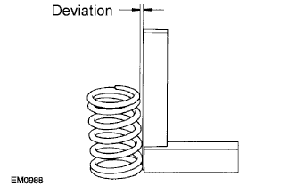
Using a steel square, measure the deviation of the spring.
Maximum deviation 2.0 mm (0.079 in.) If the deviation is greater than the maximum, replace the spring.
-
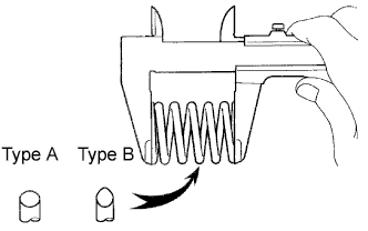
Using vernier calipers, measure the free length of the spring.
Free length Type Length Type A 46.20 mm (1.8189 in.) Type B 48.54 mm (1.9110 in.) If the free length is not as specified, replace the spring.
-
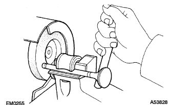
Using a spring tester, measure the tension of the valve spring at the specified installed length.
Installed tension 301 to 322 N (30.7 to 33.9 kgf, 67.7 to 74.7 lbf) at 37.00 mm (1.4567 in.) If the installed tension is not as specified, replace the spring.
-
-
INSPECT INTAKE VALVE GUIDE BUSH
-
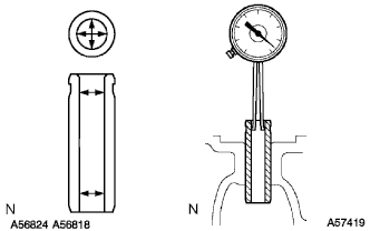
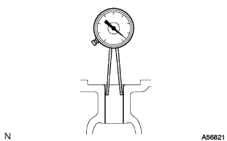
Using a caliper gauge, measure the inside diameter of the guide bush.
Bush inside diameter 8.010 to 8.030 mm (0.3154 to 0.3161 in.) -
Subtract the valve stem diameter measurement (See step 32) from the guide bush inside diameter measurement.
Standard oil clearance 0.020 to 0.055 mm (0.0008 to 0.0022 in.) Maximum oil clearance 0.08 mm (0.0031 in.) If the clearance is greater than the maximum, replace the valve and guide bush (See step 38 and 40).
-
-
INSPECT EXHAUST VALVE GUIDE BUSH
-
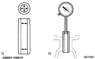
Using a caliper gauge, measure the inside diameter of the guide bush.
Bush inside diameter 8.010 to 8.030 mm (0.3154 to 0.3161 in.) -
Subtract the valve stem diameter measurement (See step 34) from the guide bush inside diameter measurement.
Standard oil clearance 0.035 to 0.070 mm (0.0014 to 0.0028 in.) Maximum oil clearance 0.10 mm (0.0039 in.) If the clearance is greater than the maximum, replace the valve and guide bush (See step 39 and 41).
-
-
REMOVE INTAKE VALVE GUIDE BUSH
-
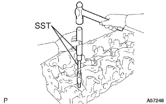
Using SST and a hammer, tap out the valve guide bushing.
- SST
- 09201-10000 ( 09201-01080 )
- 09950-70010 ( 09951-07100 )
-
-
REMOVE EXHAUST VALVE GUIDE BUSH
-
Using SST and a hammer, tap out the valve guide bushing.
- SST
- 09201-10000 ( 09201-01080 )
- 09950-70010 ( 09951-07100 )
-
-
INSTALL INTAKE VALVE GUIDE BUSH
-
Using a caliper gauge, measure the bush bore diameter of the cylinder head.
-
Select a new guide bush (STD or O/S 0.05).
Bush bore diameter Bush bore diameter Bush size 13.004 to 13.025 mm (0.5120 to 0.5128 in.) Use STD 13.054 to 13.075 mm (0.5139 to 0.5148 in.) Use O/S 0.05 If the bush bore diameter of the cylinder head is greater than 13.025 mm (0.5128 in.), machine the bush bore to dimension of 13.054 to 13.075 mm (0.5139 to 0.5148 in.).
If the bush bore diameter of the cylinder head is greater than 13.075 mm (0.5148 in.), replace the cylinder head.
-
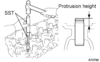
Using SST and a hammer, tap in a new guide bush to the specified protrusion height.
- SST
- 09201-10000 ( 09201-01080 )
- 09950-70010 ( 09951-07100 )
Protrusion height 10.8 to 11.2 mm (0.425 to 0.441 in.) -
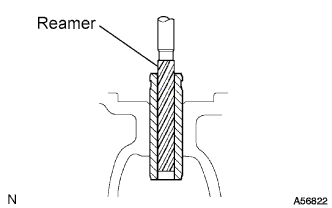
Using a sharp 8.0 mm reamer, ream the guide bush to obtain the standard specified clearance (See step 36) between the guide bush and valve stem.
-
-
INSTALL EXHAUST VALVE GUIDE BUSH
-
Using a caliper gauge, measure the bush bore diameter of the cylinder head.
-
Select a new guide bush (STD or O/S 0.05).
Bush bore diameter Bush bore diameter Bush size 13.004 to 13.025 mm (0.5120 to 0.5128 in.) Use STD 13.054 to 13.075 mm (0.5139 to 0.5148 in.) Use O/S 0.05 If the bush bore diameter of the cylinder head is greater than 13.025 mm (0.5128 in.), machine the bush bore to dimension of 13.054 to 13.075 mm (0.5139 to 0.5148 in.).
If the bush bore diameter of the cylinder head is greater than 13.075 mm (0.5148 in.), replace the cylinder head.
-
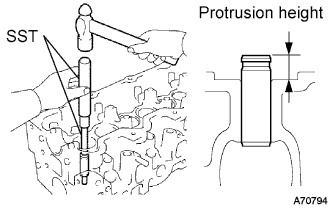
Using SST and a hammer, tap in a new guide bush to the specified protrusion height.
- SST
- 09201-10000 ( 09201-01080 )
- 09950-70010 ( 09951-07100 )
Protrusion height 10.8 mm to 11.2 mm (0.425 to 0.441 in.) -
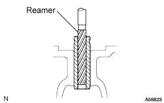
Using a sharp 8.0 mm reamer, ream the guide bush to obtain the standard specified clearance (See step 37) between the guide bush and valve stem.
-
-
INSPECT INTAKE VALVE SEATS
-
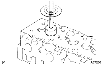
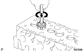
Using a 45° carbide cutter, resurface the valve seats. Remove only enough metal to clean the seats.
-
Check the valve seating position.
-
Apply a light coat of prussian blue (or white lead) to the valve face.
-
Lightly press the valve against the seat. Do not rotate valve.
-
-
Check the valve face and seat by using the following procedure:
-
If prussian blue appears around the entire valve face, the valve is concentric. If not, replace the valve.
-
If prussian blue appears around the entire valve seat, the guide and face are concentric. If not, resurface the seat.
-
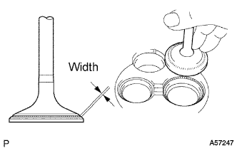
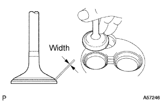
Check that the seat contacts in the middle of the valve face with the following width:
Width 1.5 to 1.9 mm (0.059 to 0.075 in.)
-
-
-
INSPECT EXHAUST VALVE SEATS
-
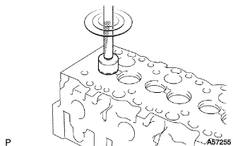
Using a 45° carbide cutter, resurface the valve seats. Remove only enough metal to clean the seats.
-
Check the valve seating position.
-
Apply a light coat of prussian blue (or white lead) to the valve face.
-
Lightly press the valve against the seat. Do not rotate valve.
-
-
Check the valve face and seat by using the following procedure:
-
If prussian blue appears around the entire valve face, the valve is concentric. If not, replace the valve.
-
If prussian blue appears around the entire valve seat, the guide and face are concentric. If not, resurface the seat.
-
Check that the seat contacts in the middle of the valve face with the following width:
Width 1.8 to 2.2 mm (0.071 to 0.087 in.)
-
-
-
REPAIR INTAKE VALVE SEATS
-
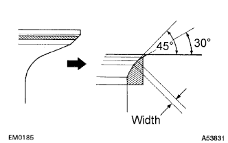
If the seating is too high on the valve face, use 30° and 45° cutters to correct the seat.
-
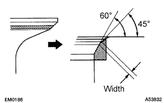
If the seating is too low on the valve face, use 60° and 45° cutters to correct the seat.
-
Handrub the valve and valve seat with an abrasive compound.
-
After handrubbing, clean the valve and valve seat.
-
-
REPAIR EXHAUST VALVE SEATS
-
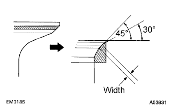
If the seating is too high on the valve face, use 30° and 45° cutters to correct the seat.
-
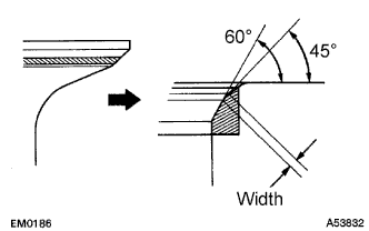
If the seating is too low on the valve face, use 60° and 45° cutters to correct the seat.
-
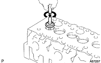
Handrub the valve and valve seat with an abrasive compound.
-
After handrubbing, clean the valve and valve seat.
-
-
INSPECT VALVE LIFTER
-
Using a micrometer, measure the lifter diameter.
Lifter diameter 40.892 to 40.902 mm (1.6099 to 1.6103 in.) -
Using a caliper gauge, measure the lifter bore diameter of the cylinder head.
Lifter bore diameter 40.960 to 40.980 mm (1.6126 to 1.6134 in.) -
Subtract the lifter diameter measurement from the lifter bore diameter measurement.
Standard oil clearance 0.058 to 0.088 mm (0.0023 to 0.0035 in.) Maximum oil clearance 0.10 mm (0.0039 in.) If the oil clearance is greater than the maximum, replace the lifter. If necessary, replace the cylinder head.
-
-
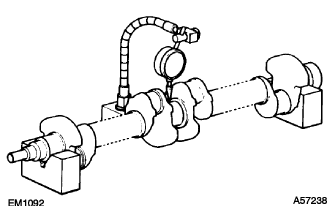
INSPECT CAMSHAFT
-
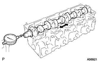
Inspect the circle runout.
-
Place the camshaft on V-blocks.
-
Using a dial indicator, measure the circle runout at the center journal.
Maximum circle runout 0.10 mm (0.0039 in.) If the circle runout is greater than the maximum, replace the camshaft.
-
-
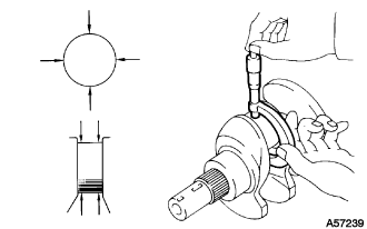
Using a micrometer, measure the cam lobe height.
Standard cam lobe height Cam lobe height Intake 54.890 to 54.910 mm (2.1610 to 2.1618 in.) Exhaust 54.990 to 55.010 mm (2.1650 to 2.1657 in.) Minimum cam lobe height Cam lobe height Intake 54.39 mm (2.1413 in.) Exhaust 54.49 mm (2.1453 in.) If the cam lobe height is less than the minimum, replace the camshaft.
-
Inspect the journal diameter of the camshaft.
-
Using a micrometer, measure the journal diameter of the camshaft for the camshaft bearing.
Journal diameter Journal Diameter STD No.1 34.969 to 34.985 mm (1.3767 to 1.3774 in.) Other 27.969 to 27.985 mm (1.1011 to 1.1018 in.) U/S 0.125 No.1 34.844 to 34.860 mm (1.3718 to 1.3724 in.) Other 27.844 to 27.860 mm (1.0962 to 1.0968 in.) U/S 0.250 No.1 34.719 to 34.735 mm (1.3669 to 1.3675 in.) Other 27.719 to 27.735 mm (1.0913 to 1.0919 in.) If the journal diameter is not as specified, check the oil clearance.
-
-
Check the oil clearance.
-
Clean the bearing caps and journals.
-
Check the bearings for flaking and scoring.
If the bearings are damaged, replace them.
-
Install the bearings to the bearing caps and cylinder head.
-
Place the camshaft on the cylinder head.
-
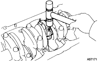
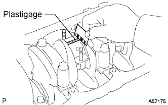
Lay a strip of Plastigage across each of the journals.
-
Install the bearing caps (See reassembly, step 37).
Note
Do not turn the camshaft.
-
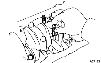
Remove the bearing caps (See step 7).
-
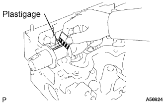
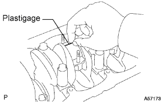
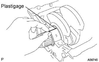
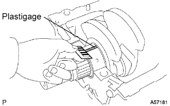
Measure the Plastigage at its widest point.
Standard oil clearance 0.022 to 0.074 mm (0.0009 to 0.0029 in.) Maximum oil clearance 0.10 mm (0.0039 in.) If the oil clearance is greater than the maximum, replace the bearings. If necessary, grind or replace the camshaft.
-
Completely remove the Plastigage.
-
Remove the camshaft.
-
-
If necessary, grind and hone the camshaft journals.
-
Grind and hone the journals to U/S diameter (See procedure (c) above). Install new journal U/S bearings.
-
-
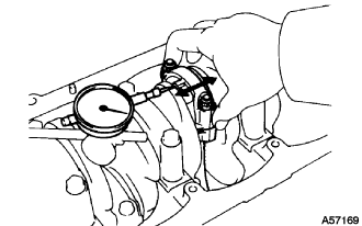
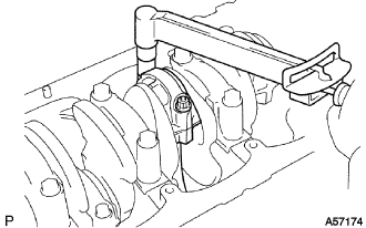
Check the thrust clearance.
-
Install the camshaft (See reassembly, step 37).
-
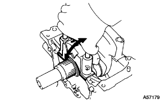
Using a dial indicator, measure the thrust clearance while moving the camshaft back and forth.
Standard thrust clearance 0.080 to 0.280 mm (0.0031 to 0.0110 in.) Maximum thrust clearance 0.35 mm (0.0138 in.) If the thrust clearance is greater than the maximum, replace the No.1 bearing. If necessary, replace the camshaft.
-
-
-
REMOVE SEMICIRCULAR PLUG
-
Remove the semicircular plug from the cylinder head.
-
-
INSPECT CONNECTING ROD THRUST CLEARANCE
Tech Tips
-
Thoroughly clean all parts to be assembled.
-
Before installing the parts, apply new engine oil to all sliding and rotating surfaces.
-
Replace all gaskets, O-rings and oil seals with new ones.
-
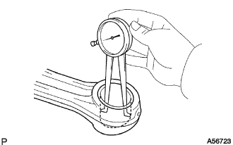
Using a dial indicator, measure the thrust clearance while moving the connecting rod back and forth.
Standard thrust clearance 0.080 to 0.300 mm (0.0031 to 0.0118 in.) Maximum thrust clearance 0.35 mm (0.0138 in.) If the thrust clearance is greater than the maximum, replace the connecting rod assembly. If necessary, replace the crankshaft.
-
-
INSPECT CONNECTING ROD OIL CLEARANCE
-
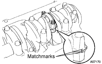
Check the matchmarks on the connecting rod and cap to ensure correct reassembly.
-
Remove the 2 connecting rod cap nuts.
-
Using a plastic hammer, lightly tap the connecting rod bolts and lift off the connecting rod cap.
Tech Tips
Keep the lower bearing inserted with the connecting rod cap.
-
Cover the connecting rod bolts with a short piece of hose to protect the crankshaft from damage.
-
Clean the crank pin and bearing.
-
Check the crank pin and bearing for pitting and scratches.
If the crank pin or bearing is damaged, replace the bearings. If necessary, grind or replace the crankshaft.
-
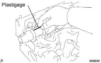
Lay a strip of Plastigage across the crank pin.
-
Install the connecting rod cap with the 2 nuts (See reassembly, step 15).
Note
Do not turn the crankshaft.
-
Remove the 2 nuts, connecting rod cap and lower bearing (See procedure (b) and (c) above).
-
Measure the Plastigage at its widest point.
Standard oil clearance Size Oil clearance STD 0.036 to 0.064 mm (0.0014 to 0.0025 in.) U/S 0.25 U/S 0.50 0.033 to 0.079 mm (0.0013 to 0.0031 in.) Maximum oil clearance 0.10 mm (0.0039 in.) If the oil clearance is greater than the maximum, replace the bearings. If necessary, grind or replace the crankshaft.
-
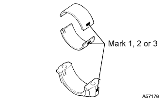
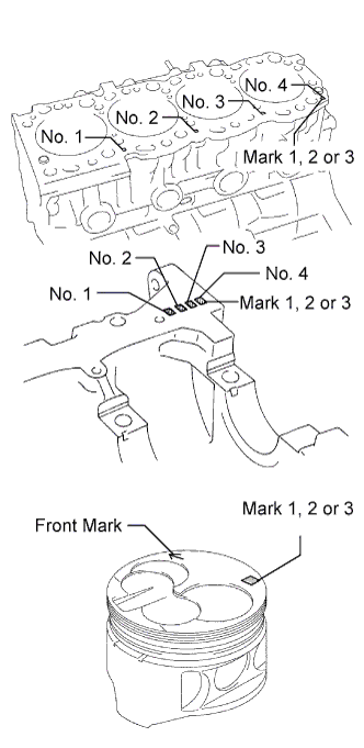
If using a standard bearing, replace it with one having the same number marked on the connecting rod cap. There are 3 sizes of standard bearings, marked 1, 2 and 3 accordingly.
Standard sized bearing center wall thickness Mark Center wall thickness 1 1.478 to 1.482 mm (0.0582 to 0.0583 in.) 2 1.482 to 1.486 mm (0.0583 to 0.0585 in.) 3 1.486 to 1.490 mm (0.0585 to 0.0587 in.)
-
Completely remove the Plastigage.
-
-
-
REMOVE PISTON AND CONNECTING ROD
-
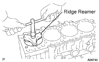
Using a ridge reamer, remove all the carbon from the top of the cylinder.
-
Cover the connecting rod bolts with a short piece of hose to protect the crankshaft from damage.
-
Push the piston, connecting rod assembly and upper bearing through the top of the cylinder block.
Tech Tips
-
Keep the bearings, connecting rod and cap together.
-
Arrange the piston and connecting rod assemblies in the correct order.
-
-
-
REMOVE PISTON SUB-ASSEMBLY W/PIN
-
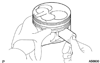
Check the fitting condition between the piston and piston pin.
-
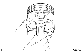
Try to move the piston back and forth on the piston pin.
If any movement is felt, replace the piston and pin as a set.
-
-
Remove the piston rings.
-
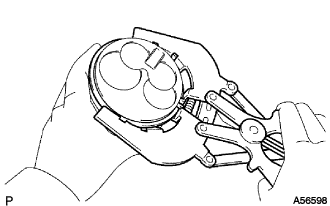
Using a piston ring expander, remove the 2 compression rings.
-
Remove the oil ring and coil by hand.
Tech Tips
Arrange the piston rings in the correct order.
-
-
Disconnect the connecting rod from the piston.
-
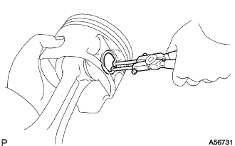
Using snap ring pliers, remove the snap rings.
-
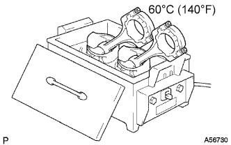
Gradually heat the piston to approx. 60°C (140°F).
-
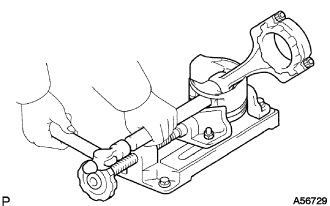
Using a plastic hammer and brass bar, lightly tap out the piston pin and remove the connecting rod.
Tech Tips
-
The piston and pin are a matched set.
-
Arrange the pistons, pins, rings, connecting rods and bearings in the correct order.
-
-
-
-
INSPECT CRANKSHAFT THRUST CLEARANCE
-
Using a dial indicator, measure the thrust clearance while prying the crankshaft back and forth with a screwdriver.
Standard thrust clearance 0.040 to 0.250 mm (0.0016 to 0.0098 in.) Maximum thrust clearance 0.30 mm (0.0118 in.) If the thrust clearance is greater than the maximum, replace the thrust washers as a set.
Thrust washer thickness Size Thickness STD 2.430 to 2.480 mm (0.0957 to 0.0976 in.) O/S 0.125 2.493 to 2.543 mm (0.0981 to 0.1001 in.) O/S 0.250 2.555 to 2.605 mm (0.1006 to 0.1026 in.)
-
-
INSPECT CRANKSHAFT OIL CLEARANCE
-
Remove the 10 crankshaft bearing cap bolts.
-
Using the removed crankshaft bearing cap bolts, pry the cap back and forth, and remove the crankshaft bearing caps, lower bearings and lower thrust washers (No.3 crankshaft bearing cap only).
Tech Tips
-
Keep the lower bearing and crankshaft bearing caps together.
-
Arrange the thrust washers in the correct order.
-
-
Lift out the crankshaft.
Tech Tips
Keep the upper crankshaft bearings and upper thrust washers together with the cylinder block.
-
Clean each main journal and bearing.
-
Check each main journal and bearing for pitting and scratches.
If the journal or bearing is damaged, replace the bearings. If necessary, grind or replace the crankshaft.
-
Place the crankshaft on the cylinder block.
-
Lay a strip of Plastigage across each journal.
-
Install the 5 crankshaft bearing caps with the 10 bolts (See reassembly, step 14).
Note
Do not turn the crankshaft.
-
Remove the 10 bolts and 5 crankshaft bearing caps (See procedure (a) and (b) above).
-
Measure the Plastigage at its widest point.
Standard oil clearance Size Oil clearance STD 0.034 to 0.065 mm (0.0013 to 0.0026 in.) U/S 0.25, U/S 0.50 0.033 to 0.079 mm (0.0013 to 0.0031 in.) Maximum oil clearance 0.10 mm (0.0039 in.) If the oil clearance is greater than the maximum, replace the bearings. If necessary, grind or replace the crankshaft.
-
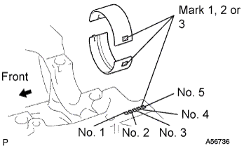
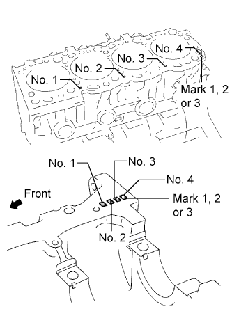
If using a standard bearing, replace it with one having the same number marked on the connecting rod cap. There are 3 sizes of standard bearings, marked 1, 2 and 3 accordingly.
Standard sized bearing center wall thickness Mark Center wall thickness 1 1.979 to 1.983 mm (0.0779 to 0.0781 in.) 2 1.983 to 1.987 mm (0.0781 to 0.0782 in.) 3 1.987 to 1.991 mm (0.0782 to 0.0784 in.) -
Completely remove the Plastigage.
-
-
REMOVE CRANKSHAFT
-
Lift out the crankshaft.
-
Remove the upper bearings and upper thrust washers from the cylinder block.
Tech Tips
Arrange the crankshaft bearing caps, bearings and thrust washers in the correct order.
-
-
REMOVE OIL NOZZLE NO.1 SUB-ASSEMBLY
-
Remove the 4 check valves and oil nozzles.
-
-
INSPECT OIL CHECK VALVE SUB-ASSEMBLY
-
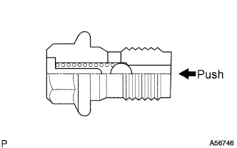
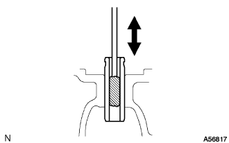
Push the valve with a wooden stick to check if it is stuck.
If stuck, replace the check valve.
-
-
INSPECT OIL NOZZLE NO.1 SUB-ASSEMBLY
-
Check the oil nozzles for damage or clogging.
If necessary, replace the oil nozzle.
-
-
REMOVE CYLINDER BLOCK OIL ORIFICE
-
Using a 6 mm hexagon wrench, remove the oil orifice.
-
-
INSPECT CYLINDER BLOCK OIL ORIFICE
-
Check the oil orifice for damage or clogging.
If necessary, replace the oil orifice.
-
-
REMOVE CYLINDER BLOCK WATER DRAIN COCK SUB-ASSEMBLY
-
Remove the water drain cock from the cylinder block.
-
-
REMOVE W/HEAD TAPER SCREW PLUG NO.1
-
Remove the screw plug from the cylinder block.
-
-
CLEAN CYLINDER BLOCK SUB-ASSEMBLY
-
Using a gasket scraper, remove all the gasket material from the top surface of the cylinder block.
-
Using a soft brush and solvent, thoroughly clean the cylinder block.
-
-
INSPECT CYLINDER BLOCK SUB-ASSEMBLY
-
Inspect for warpage.
-
Using a precision straight edge and feeler gauge, measure the surface contacting the cylinder head cap for warpage.
Maximum warpage 0.20 mm (0.0079 in.) If warpage is greater than the maximum, replace the cylinder block.
-
-
Visually check the cylinder for vertical scratches.
If deep scratches are present, rebore all the 4 cylinders. If necessary, replace the cylinder block.
-
Inspect the cylinder bore diameter.
Tech Tips
There are 3 sizes of the standard cylinder bore diameter, marked 1, 2 and 3 accordingly. The mark is stamped on the lower left rear of the cylinder block.
-
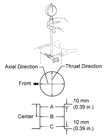
Using a cylinder gauge, measure the cylinder bore diameter at positions A, B and C in the thrust and axial directions.
Standard diameter Mark Diameter 1 99.500 to 99.510 mm (3.9173 to 3.9177 in.) 2 99.510 to 99.520 mm (3.9177 to 3.9181 in.) 3 99.520 to 99.530 mm (3.9181 to 3.9185 in.) Maximum diameter Diameter STD 99.73 mm (3.9264 in.) O/S 0.50 100.23 mm (3.9461 in.) If the diameter is greater than the maximum, rebore all the 4 cylinders. If necessary, replace the cylinder block.
-
-
Remove the cylinder ridge.
If the wear is less than 0.2 mm (0.008 in.), using a ridge reamer, grind the top of the cylinder.
-
-
CLEAN PISTON SUB-ASSEMBLY W/PIN
-
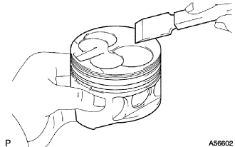
Using a gasket scraper, remove the carbon from the piston top.
-
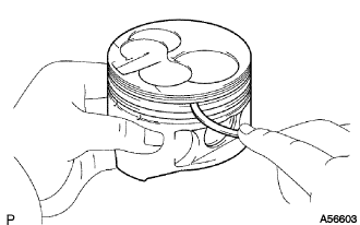
Using a groove cleaning tool or broken ring, clean the piston ring grooves.
-
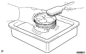
Using solvent and a brush, thoroughly clean the piston.
Note
Do not use a wire brush.
-
-
INSPECT PISTON SUB-ASSEMBLY W/PIN
Tech Tips
-
When replacing the piston and pin as a set with a supply part, there are a number of piston diameter sizes to choose from, but there is only one size of piston pin diameter.
-
There are 3 sizes of the standard piston diameter, marked "1", "2" and "3" accordingly. The mark is stamped on the piston top.
-
Inspect the piston oil clearance.
-
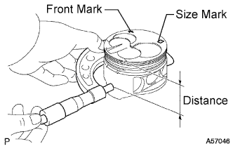
Using a micrometer, measure the piston diameter at right angles to the piston center line where the distance from the piston head is as specified.
Distance 61.27 to 61.33 mm (2.4122 to 2.4146 in.) Piston diameter Size Diameter STD Mark 1 99.450 to 99.460 mm (3.9153 to 3.9157 in.) STD Mark 2 99.460 to 99.470 mm (3.9157 to 3.9161 in.) STD Mark 3 99.470 to 99.480 mm (3.9161 to 3.9165 in.) O/S 0.50 99.950 to 99.980 mm (3.9350 to 3.9362 in.) -
Measure the cylinder bore diameter in the thrust direction (See step 64).
-
Subtract the piston diameter measurement from the cylinder bore diameter measurement.
Standard oil clearance 0.040 to 0.060 mm (0.0016 to 0.0024 in.) Maximum oil clearance 0.13 mm (0.0051 in.) If the oil clearance is greater than the maximum, replace all the 4 pistons and rebore all the 4 cylinders. If necessary, replace the cylinder block.
-
-
Use a piston with the same number mark as the cylinder bore diameter marked on the cylinder block.
-
Inspect the piston pin fitting condition.
-
Check that the piston pin is pushed into the piston pin hole with your thumb at 60°C (140°F).
If the pin can be installed at a lower temperature, replace the piston and pin as a set.
-
-
Using a micrometer, measure the piston pin diameter.
Piston pin diameter 29.000 to 29.012 mm (1.1417 to 1.1422 in.)
-
-
INSPECT PISTON RING SET
-
Inspect the piston ring groove clearance.
-
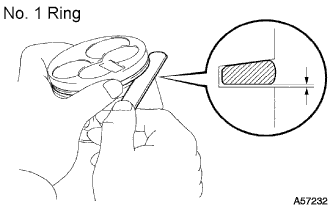
No. 1 Ring: Install a new piston ring to the piston. Using a feeler gauge, measure the clearance between the piston ring and the wall of the ring groove.
Standard groove clearance 0.057 to 0.101 mm (0.0022 to 0.0040 in.) Maximum groove clearance 0.20 mm (0.0079 in.) If the clearance is greater than the maximum, replace the piston.
-
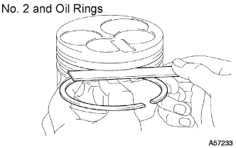
No. 2 and Oil Rings: Using a feeler gauge, measure the clearance between a new piston ring and the wall of the ring groove.
Standard groove clearance Ring Groove clearance No. 2 0.060 to 0.100 mm (0.0024 to 0.0039 in.) Oil 0.030 to 0.070 mm (0.0012 to 0.0028 in.) Maximum groove clearance 0.20 mm (0.0079 in.) If the clearance is greater than the maximum, replace the piston.
-
-
Inspect the piston ring end gap.
-

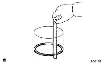
Insert the piston ring into the cylinder bore.
-
Using a piston, push the piston ring a little beyond the bottom of the ring travel, 140 mm (5.51 in.) from the top of the cylinder block.
-
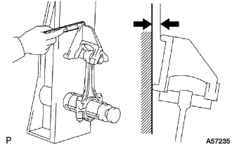
Using a feeler gauge, measure the end gap.
Standard end gap Ring End gap No. 1 0.350 to 0.590 mm (0.0138 to 0.0232 in.) No. 2 0.470 to 0.720 mm (0.0185 to 0.0283 in.) Oil 0.200 to 0.520 mm (0.0079 to 0.0205 in.) Maximum end gap Ring End gap No. 1 1.29 mm (0.0508 in.) No. 2 1.42 mm (0.0559 in.) No. 3 1.22 mm (0.0480 in.) If the end gap is greater than the maximum, replace the piston ring.
If the end gap is greater than the maximum, even with a new piston ring, rebore all the 4 cylinders or replace the cylinder block.
-
-
-
INSPECT CONNECTING ROD SUB-ASSEMBLY
-
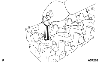
Using a rod aligner and feeler gauge, check the connecting rod alignment.
-
Check for bend.
Maximum bend 0.05 mm (0.0020 in.) per 100 mm (3.94 in.) If bend is greater than the maximum, replace the connecting rod sub-assembly.
-
Check for twist
Maximum twist 0.15 mm (0.0059 in.) per 100 mm (3.94 in.) If twist is greater than the maximum, replace the connecting rod sub-assembly.
-
-
-
INSPECT PISTON PIN OIL CLEARANCE
Tech Tips
When replacing the piston and pin as a set with a supply part, there are a number of piston diameter sizes to choose from, but there is only one size of piston pin diameter.
-
Inspect the piston pin oil clearance.
-
Using a caliper gauge, measure the inside diameter of the connecting rod bush.
Bush inside diameter 29.008 to 29.020 mm (1.1420 to 1.1425 in.) -
Subtract the piston pin diameter measurement (See step 66) from the bush inside diameter measurement.
Standard oil clearance 0.004 to 0.012 mm (0.0002 to 0.0005 in.) Maximum oil clearance 0.05 mm (0.0020 in.) If the oil clearance is greater than the maximum, replace the bush.
If necessary, replace the piston and piston pin as a set.
-
-
-
REMOVE CONNECTING ROD SMALL END BUSH
-
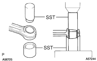
Using SST and a press, press out the bush.
- SST
- 09222-54011 ( 09222-03016, 09222-03026 )
-
-
INSPECT CONNECTING ROD BOLT
-
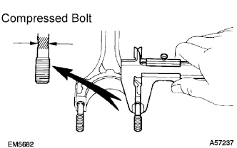
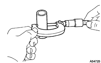
Using vernier calipers, measure the tension portion diameter of the connecting rod bolt.
Standard diameter 8.400 to 8.600 mm (0.3307 to 0.3386 in.) Minimum diameter 8.20 mm (0.3228 in.) If the diameter is less than the minimum, replace the bolt.
-
-
BORE CYLINDER
Tech Tips
-
Bore all the 4 cylinders to fit the O/S piston outside diameter.
-
Replace all the piston rings with ones to match the O/S pistons.
-
Prepare 4 new O/S pistons.
O/S 0.50 piston diameter 99.950 to 99.980 mm (3.9350 to 3.9362 in.) -
Using a micrometer, measure the piston diameter at right angles to the piston pin center line where the distance from the piston head is as specified.
Distance 61.27 to 61.33 mm (2.4122 to 2.4146 in.) -
Calculate the amount each cylinder is to be rebored as follows:
Tech Tips
-
Size to be rebored = P + C - H
-
P = Piston diameter
-
C = Piston clearance: 0.040 to 0.060 mm (0.0016 to 0.0024 in.)
-
H = Allowance for honing: 0.02 mm (0.0008 in.) or less
-
-
Bore and hone the cylinders to the calculated dimensions.
Maximum honing 0.02 mm (0.0008 in.) Note
Excess honing will destroy the finished roundness.
-
-
INSPECT CRANKSHAFT
-
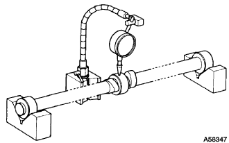
Inspect for circle runout.
-
Place the crankshaft on V-blocks.
-
Using a dial indicator, measure the circle runout at the center journal.
Maximum circle runout 0.06 mm (0.0024 in.) If the circle runout is greater than the maximum, replace the crankshaft.
-
-
Inspect the main journals and crank pins.
-
Using a micrometer, measure the diameter of each main journal and crank pin.
Main journal diameter Size Diameter STD 61.985 to 62.000 mm (2.4403 to 2.4409 in.) U/S 0.25 61.745 to 61.755 mm (2.4309 to 2.4313 in.) U/S 0.50 61.495 to 61.505 mm (2.4211 to 2.4215 in.) Crank pin diameter Size Diameter STD 54.988 to 55.000 mm (2.1649 to 2.1654 in.) U/S 0.25 54.745 to 54.755 mm (2.1553 to 2.1557 in.) U/S 0.50 54.495 to 54.505 mm (2.1455 to 2.1459 in.) If the diameter is not as specified, check the oil clearance (See steps 50 and 54). If necessary, grind or replace the crankshaft.
-
Check each main journal and crank pin for taper and out-of-round as shown.
Maximum taper and out-of-round 0.02 mm (0.0008 in.) If the taper and out-of-round is greater than the maximum, replace the crankshaft.
-
-
If necessary, grind and hone the main journals and/or crank pins.
-
Grind and hone the main journals and/or crank pins to the finished undersized diameter (See procedure in step (b) above).
-
Install new main journal and/or crankshaft pin undersized bearing.
-
-