CYLINDER HEAD INSTALLATION

Tech Tips
Perform "Inspection After Repairs" after replacing the camshaft, No. 2 camshaft or cylinder head sub-assembly Click here.
-
INSTALL CYLINDER HEAD GASKET
-
Remove any old packing (FIPG) material and be careful not to drop any oil on the contact surfaces of the cylinder head sub-assembly or cylinder block.
-
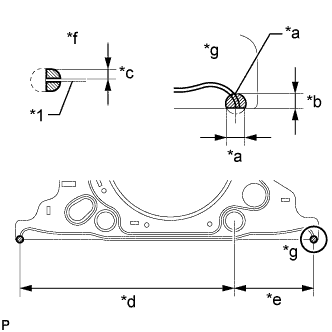
Text in Illustration *1 Cylinder Head Gasket *a 7.0 to 9.0 mm (0.276 to 0.354 in.) *b 5.0 to 7.0 mm (0.197 to 0.276 in.) *c 3.0 to 5.0 mm (0.118 to 0.197 in.) *d 166.25 mm (6.55 in.) *e 62.25 mm (2.46 in.) *f Side View *g View A Apply seal packing to a new cylinder head gasket as shown in the illustration.
Seal Packing Toyota Genuine Seal Packing Black, Three Bond 1207 B or equivalent. Note
-
Be sure to clean and degrease the contact surfaces.
-
Apply seal packing to the bead on the cylinder head gasket.
-
Install the cylinder head gasket within 3 minutes and tighten the cylinder head set bolts within 15 minutes after applying seal packing.
-
-
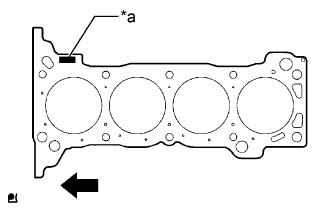
Text in Illustration *a Lot No. 
Engine Front Place the gasket on the cylinder block surface with the lot No. stamp facing upward.
Note
-
Remove any oil from the contact surface.
-
Make sure that the cylinder head gasket is installed in the correct direction.
-
-
-
INSTALL CYLINDER HEAD SUB-ASSEMBLY
Tech Tips
-
Perform "Inspection After Repairs" after replacing the cylinder head sub-assembly Click here.
-
The cylinder head set bolts are tightened in 3 successive steps.
-
Place the cylinder head sub-assembly on the cylinder block.
Note
-
Make sure that no oil is on the mounting surface of the cylinder head sub-assembly.
-
Place the cylinder head sub-assembly on the cylinder block gently so as not to damage the gasket with the bottom part of the head.
-
-
Install the plate washers to the cylinder head set bolts.
-
Apply a light coat of engine oil to the threads and under the heads of the cylinder head set bolts.
-
Step 1:
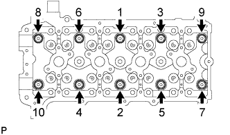
Using several steps, install and uniformly tighten the 10 cylinder head set bolts with plate washers in the sequence shown in the illustration.
- Torque:
- 39 N*m { 398 kgf*cm, 29 ft.*lbf }
-
Mark the front of each cylinder head set bolt head with paint.
-
Step 2:
Tighten the cylinder head set bolts 90° in the sequence shown in step 1.
-
Step 3:
Tighten the cylinder head set bolts another 90° in the sequence shown in step 1.
-
Check that the paint marks are now at a 180° angle to the front.
-
-
INSTALL VALVE STEM CAP
-
Apply a light coat of engine oil to the valve stem ends.
-
Install the 16 valve stem caps to the cylinder head sub-assembly.
Note
Do not drop the valve stem caps into the cylinder head sub-assembly.
-
-
INSTALL VALVE LASH ADJUSTER ASSEMBLY
-
Inspect each valve lash adjuster assembly before installing it Click here.
-
Install the 16 valve lash adjuster assemblies to the cylinder head sub-assembly.
Note
Install each valve lash adjuster assembly to the same place it was removed from.
-
-
INSTALL NO. 1 VALVE ROCKER ARM SUB-ASSEMBLY
-
Apply clean engine oil to the valve lash adjuster assembly tips and valve stem cap surfaces.
-
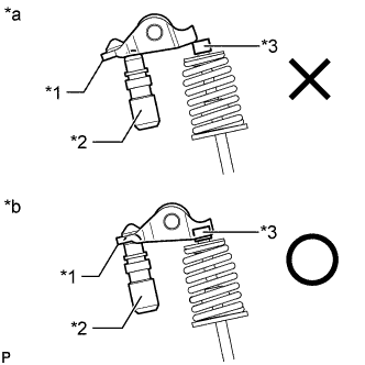
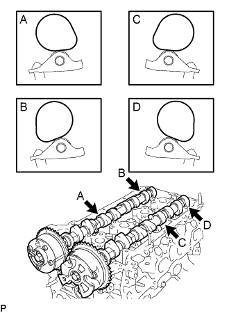
Text in Illustration *1 No. 1 Valve Rocker Arm Sub-assembly *2 Valve Lash Adjuster Assembly *3 Valve Stem Cap *a INCORRECT *b CORRECT Install the 16 No. 1 valve rocker arm sub-assemblies as shown in the illustration.
Note
Install the valve stem cap, valve lash adjuster assembly and No. 1 valve rocker arm sub-assembly to the same places they were removed from.
-
-
INSTALL CAMSHAFTS
Tech Tips
Perform "Inspection After Repairs" after replacing the camshaft or No. 2 camshaft Click here.
-
Apply clean engine oil to the camshaft cams and cylinder head journals.
-
Position the camshaft and No. 2 camshaft as shown in the illustration.
-
Text in Illustration *1 No. 1 Valve Rocker Arm Sub-assembly *2 Valve Lash Adjuster Assembly *3 Valve Stem Cap *a INCORRECT *b CORRECT Make sure that the No. 1 valve rocker arm sub-assemblies are installed as shown in the illustration.
-
-
INSTALL CAMSHAFT BEARING CAP
-

Temporarily install the No. 1 camshaft bearing cap.
-
Confirm the location for each No. 2 camshaft bearing cap and install each one to the proper location.
-
Uniformly temporarily install the 20 bolts while keeping the camshaft level.
-
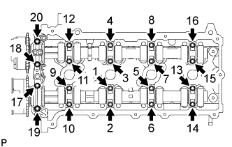
Tighten the 20 bolts in the order shown in the illustration.
- Torque:
- 16 N*m { 158 kgf*cm, 11 ft.*lbf }
-
-
INSTALL NO. 1 CHAIN VIBRATION DAMPER
-
Install the No. 1 chain vibration damper with the 2 bolts.
- Torque:
- 21 N*m { 214 kgf*cm, 15 ft.*lbf }
-
-
INSTALL CHAIN SUB-ASSEMBLY
-
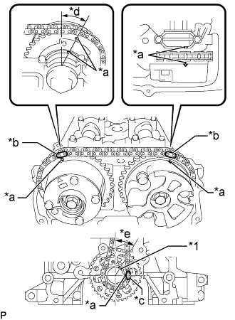
Text in Illustration *1 Key *a Timing Mark *b Mark Plate (Yellow) *c Mark Plate (Pink) *d Approximately 13° *e Approximately 30° As shown in the illustration, install the chain sub-assembly to the camshaft timing exhaust gear assembly and camshaft timing gear assembly with the mark plates aligned with the timing marks on the camshaft timing exhaust gear assembly and camshaft timing gear assembly.
Tech Tips
-
The camshaft mark plate is yellow.
-
The crankshaft mark plate is pink.
-
-
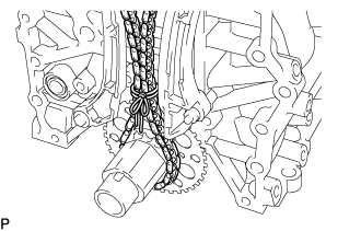
Use a rope to secure the chain sub-assembly of the crankshaft timing gear or sprocket. Tie the rope near the crankshaft timing gear or sprocket.
Note
After the No. 1 chain tensioner assembly has been installed, the rope must be removed.
Tech Tips
The rope is used to prevent the chain sub-assembly from jumping a tooth.
-
-
INSTALL CHAIN TENSIONER SLIPPER
-
Install the chain tensioner slipper with the bolt.
- Torque:
- 21 N*m { 214 kgf*cm, 15 ft.*lbf }
-
-
INSTALL NO. 1 CHAIN TENSIONER ASSEMBLY
-
Install a new gasket and the No. 1 chain tensioner assembly with the bolt and nut.
- Torque:
- 10 N*m { 102 kgf*cm, 7 ft.*lbf }
Note
Remove the hexagon wrench after installing the timing chain guide.
-
-
INSTALL TIMING CHAIN GUIDE
-
Text in Illustration *1 O-ring Install a new O-ring and the timing chain guide with the 2 bolts.
- Torque:
- 10 N*m { 102 kgf*cm, 7 ft.*lbf }
-
-
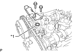
INSTALL CYLINDER HEAD COVER CONNECTOR SUB-ASSEMBLY
-
Install a new No. 2 camshaft bearing cap oil hole gasket and 3 new No. 3 camshaft bearing cap oil hole gaskets to the camshaft bearing cap.
-
Install the cylinder head cover connector sub-assembly with the 2 bolts.
- Torque:
- 10 N*m { 102 kgf*cm, 7 ft.*lbf }
-
-
CHECK NO. 1 CYLINDER TO TDC/COMPRESSION
-
Check that the No. 1 cylinder is set to TDC/compression.
-

Text in Illustration *1 Key *a Timing Mark *b Approximately 13° *c Approximately 30° Rotate the crankshaft two full rotations, and then check that all timing marks are in the position shown in the illustration.
If the timing marks do not match, set the chain sub-assembly again.
-
-
-
INSTALL EXHAUST MANIFOLD
-
INSTALL INTAKE MANIFOLD
-
INSTALL TIMING CHAIN OR BELT COVER SUB-ASSEMBLY
-
INSTALL AUTOMATIC TRANSMISSION ASSEMBLY
-
INSPECT IGNITION TIMING
-
Warm up and stop the engine.
Note
A warmed up engine should have an engine coolant temperature of over 80°C (176°F), have an engine oil temperature of 60°C (140°F), and the engine speed should be stabilized.
-
When using the intelligent tester:
-
Connect the intelligent tester to the DLC3.
-
Start the engine and idle it.
-
Turn the intelligent tester main switch on.
-
Enter the following menus:
Powertrain / Engine and ECT / Data List / IGN Advance
Standard ignition timing 5 to 15° BTDC at idle Note
When checking the ignition timing, the transmission should be in neutral or park.
Tech Tips
Refer to the intelligent tester operator's manual for further detail.
-
-
When not using the intelligent tester:
-
Connect the tester probe of a timing light to the wire of the ignition coil connector for the No.4 cylinder.
Note
-
Use a timing light that detects primary signals.
-
After checking, be sure to wrap the wire harness with tape.
-
-
Start the engine and idle it.
-
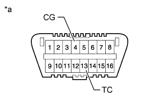
Using SST, connect terminals 13 (TC) and 4 (CG) of the DLC3.
- SST
- 09843-18040
Text in Illustration *a Front view of DLC3 Note
-
Confirm the terminal numbers before connecting them. Connecting the wrong terminals can damage the engine.
-
When checking the ignition timing, the transmission should be in neutral or park.
Tech Tips
-
-
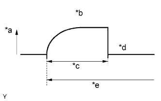
After connecting terminals (TC and CG), engine speed changes to approximately 1000 to 1500 rpm for 5 seconds, and then returns to idle speed. This is because the ECM checks that the ISC (idle speed control system) operates properly.
-
Perform the inspection of the ignition timing after engine speed is returned to idle speed.
Text in Illustration *a Engine Speed *b Approx. 1000 to 1500 rpm *c 5 sec. *d Idle Speed *e Connect Terminals TC and CG -
Inspect the ignition timing
Standard ignition timing 3 to 7° BTDC at idle -
Disconnect terminals 13 (TC) and 4 (CG) of the DLC3.
-
Inspect the ignition timing
Standard ignition timing 5 to 15° BTDC at idle -
Check that the ignition timing advances immediately when the engine speed is increased.
-
Turn the ignition switch off.
-
Remove the timing light.
-
-
-
INSPECT ENGINE IDLE SPEED
-
Warm up and stop the engine.
-
When using the intelligent tester:
-
Connect the intelligent tester to the DLC3.
Tech Tips
Refer to the intelligent tester operator's manual for further details.
-
Start the engine and idle it.
-
Turn the intelligent tester main switch on.
-
Enter the following menus:
Powertrain / Engine and ECT / Data List / Engine SPD
Idle speed 650 to 750 rpm Note
-
When checking the idle speed, the transmission should be in the neutral position.
-
Switch off all accessories and air conditioning before connecting the intelligent tester.
-
-
Turn the ignition switch off.
-
Disconnect the intelligent tester from the DLC3.
-
-
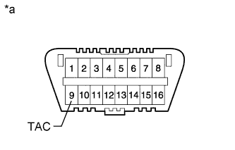
Text in Illustration *a Front view of DLC3 When not using the intelligent tester:
-
Install SST to terminal 9 (TAC) of DLC3, and then connect a tachometer.
- SST
- 09843-18030
Note
Confirm the terminal numbers before connecting them. Connecting the wrong terminals can damage the engine.
-
Start the engine and idle it.
-
Inspect the engine idling speed.
Idle speed 650 to 750 rpm -
Turn the ignition switch off.
-
Disconnect the tachometer.
-
Remove SST from terminal 9 (TAC).
-
-
-
INSPECT CO/HC
-
Start and warm up the engine.
-
Run the engine at 2500 rpm for approximately 180 seconds.
-
Insert the CO/HC meter testing probe at least 40 cm (1.31 ft.) into the tailpipe while idling.
-
Immediately check the CO/HC concentration at idle and at 2500 rpm.
Tech Tips
-
When performing the 2-mode (2500 rpm and idle) test, follow the measurement order prescribed by the applicable local regulations.
-
If the CO/HC concentration does not comply with regulations, troubleshoot in the order given below.
-
-
If the CO/HC concentration is not as specified, perform troubleshooting in the order given below.
-
Check the air fuel ratio sensor Click here and heated oxygen sensor Click here operation.
-
See the table below for possible causes, and then inspect and repair the applicable causes if necessary.
CO HC Problems Causes Normal High Rough idle
-
Faulty ignitions:
-
Incorrect timing
-
Fouled, shorted or improperly gapped plugs
-
Incorrect valve clearance
-
Leaks in intake and exhaust valves
-
Leaks in cylinders
Low High Rough idle
(Fluctuating HC reading)
-
Vacuum leaks:
-
PCV hoses
-
Intake manifold
-
Throttle body
-
Brake booster line
-
Lean mixture causing misfire
High High Rough idle
(Black smoke from exhaust)
-
Restricted air filter
-
Plugged PCV valve
-
Faulty SFI systems:
-
Faulty pressure regulator
-
Defective engine coolant temperature sensor
-
Defective mass air flow meter
-
Faulty ECM
-
Faulty injectors
-
Faulty throttle body
-
-
-