ENGINE ASSEMBLY REMOVAL

-
PLACE FRONT WHEELS FACING STRAIGHT AHEAD
-
SEPARATE BATTERY NEGATIVE CABLE
-
REMOVE FRONT WHEELS
-
REMOVE ENGINE UNDER COVER NO.1 (w/ Engine Under Cover No.1)
-
REMOVE ENGINE UNDER COVER NO.2 (w/ Engine Under Cover No.2)
-
REMOVE ENGINE SIDE UNDER COVER LH (w/ Engine Side Under Cover LH)
-
REMOVE ENGINE SIDE UNDER COVER RH (w/ Engine Side Under Cover RH)
-
DRAIN POWER STEERING FLUID
-
DRAIN ENGINE COOLANT
CAUTION:
Do not remove the radiator reservoir cap sub-assembly while the engine and radiator are still hot. Pressurized, hot engine coolant and steam may be released and cause serious burns.
-
Loosen the radiator drain cock plug.
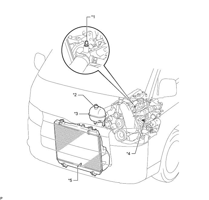
Text in Illustration *1 Bleeder Plug *2 Radiator Reservoir Cap Sub-assembly *3 Radiator Reservoir Assembly *4 Cylinder Block Drain Cock Plug *5 Radiator Drain Cock Plug - - -
Remove the radiator reservoir cap sub-assembly.
-
Loosen the cylinder block drain cock plug (on the engine oil cooler cover), and drain the engine coolant.
-
Tighten the radiator drain cock plug.
-
Tighten the cylinder block drain cock plug (on the engine oil cooler cover).
- Torque:
- 8.0 N*m { 82 kgf*cm, 71 in.*lbf }
-
-
DRAIN ENGINE OIL
-
Remove the oil filler cap.
-
Remove the oil drain plug, and drain the engine oil from the oil pan.
-
Install a new gasket and the drain plug.
- Torque:
- 34 N*m { 347 kgf*cm, 25 ft.*lbf }
-
-
REMOVE FRONT SEAT ASSEMBLY RH (for Hi-back Seat Type)
-
Perform the same procedure as above on the opposite side. Click here
-
-
REMOVE FRONT SEAT ASSEMBLY RH (for Low-back Seat Type)
-
Perform the same procedure as above on the opposite side. Click here
-
-
REMOVE FRONT DOOR SCUFF PLATE RH
-
REMOVE ENGINE SERVICE HOLE SUB COVER ASSEMBLY
-
Roll up the carpet, and remove the engine service hole sub cover assembly.
-
-
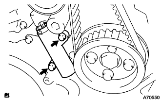
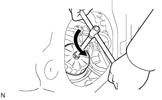
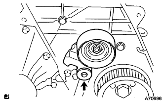
REMOVE FAN & GENERATOR V BELT
-
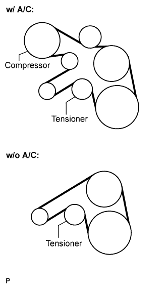
Remove the drive belt by rotating the tensioner pulley in clockwise direction to loosen its tension with the pulley set bolt of the tensioner.
-
-
REMOVE FENDER APRON MUDGUARD SEAL
-
REMOVE AIR CLEANER HOSE ASSEMBLY
-
Remove the bolt and air cleaner hose assembly.
-
-
REMOVE COMPRESSOR OUTLET ELBOW
-
Remove the 2 bolts and 2 clamps, then remove the compressor outlet elbow.
-
-
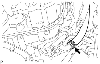
DISCONNECT OIL RETURN HOSE (w/ Intercooler)
-
Disconnect the oil return hose from the intake manifold.
-
-
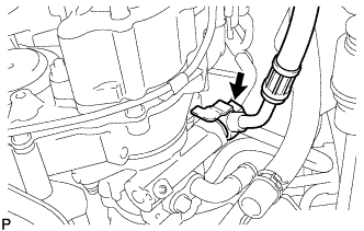
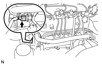
DISCONNECT AIR HOSE NO.4
-
Remove the clamp, and disconnect the air hose No.4 from the diesel throttle body.
-
-
DISCONNECT RADIATOR HOSE INLET
-
Remove the clamp, and disconnect the radiator inlet hose from the water inlet.
-
-
DISCONNECT RADIATOR HOSE NO.4
-
Remove the clamp, and disconnect the radiator hose No.4 from the water outlet.
-
-
DISCONNECT WATER BY-PASS HOSE NO.3
-
Remove the clamp, and disconnect the water by-pass hose No.3 from the water by-pass pipe.
-
-
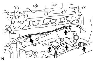
DISCONNECT FUEL HOSE NO.2
-
Remove the clamp, and disconnect the fuel hose No.2 from the nozzle leakage pipe No.2.
-
-
DISCONNECT FUEL HOSE NO.1
-
Remove the clamp, and disconnect the fuel hose No.1 from the injection pump assembly.
-
-
DISCONNECT VACUUM HOSE
-
Disconnect the vacuum hose from the vacuum pump assembly.
-
-
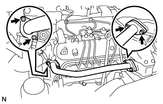
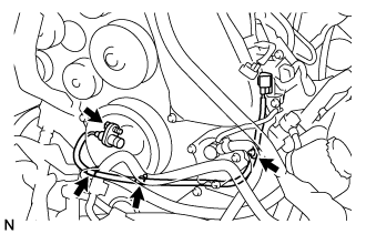
DISCONNECT ENGINE WIRE
-
Disconnect the ECM connector Click here.
-
Disconnect the clamps of the engine wire and earth cable.
-
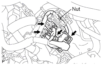
Remove the 4 connectors and nut as shown in the illustration.
-
-
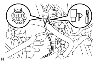
SEPARATE COMPRESSOR AND MAGNETIC CLUTCH (w/ Air Conditioning System)
-
Disconnect the connector.
-
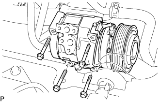
Remove the 4 bolts and compressor and magnetic clutch.
-
-
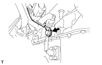
SEPARATE VANE PUMP OIL RESERVOIR ASSEMBLY
-
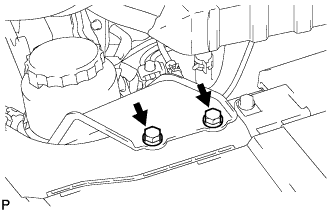
Remove the 2 bolts and vane pump oil reservoir assembly.
Note
Suspend the vane pump oil reservoir assembly with wire to prevent power steering fluid from spilling out.
-
-
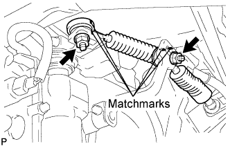
REMOVE EXHAUST PIPE ASSEMBLY FRONT (for Super Long Wheelbase)
-
Remove the 4 bolts, 2 nuts, 2 compression springs. exhaust pipe assembly front and 2 gaskets.
-
Disconnect the exhaust pipe support, and remove the exhaust pipe assembly front and 2 gaskets.
-
-
REMOVE EXHAUST PIPE ASSEMBLY FRONT (for Long Wheelbase)
-
Remove the 4 bolts, 2 nuts and 2 compression springs. 2 gasket and exhaust pipe assembly front.
-
Disconnect the exhaust pipe support, and remove the exhaust pipe assembly front and 2 gaskets.
-
-
REMOVE EXHAUST PIPE ASSEMBLY CENTER (for Super Long Wheelbase)
-
Remove the 2 bolts.
-
Disconnect the exhaust pipe supports, and remove the exhaust pipe assembly center and gasket.
-
-
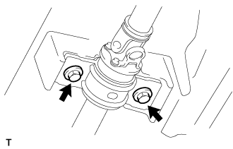
REMOVE PROPELLER WITH CENTER BEARING SHAFT ASSEMBLY (for Super Long Wheelbase)
-
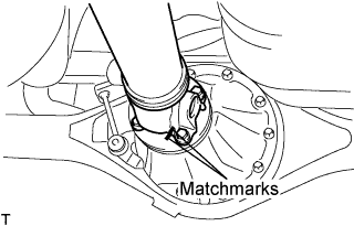
Put matchmarks on both flanges.
-
Remove the 4 nuts, bolts and washers.
Tech Tips
If the flange connection is hard to separate, temporarily tighten one nut only and evenly tap the flange with a brass bar and hammer to separate the propeller with center bearing shaft assembly from the differential companion flange.
-
Remove the 2 bolts and center support bearing assembly No.1.
-
Remove the propeller with center bearing shaft assembly.
-
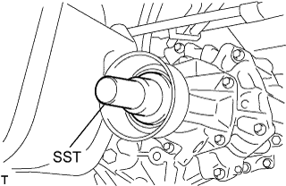
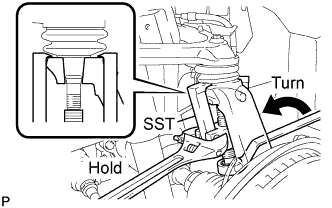
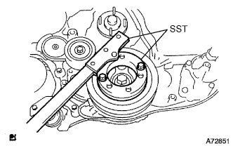
Insert SST in the transmission to prevent oil leakage.
Note
Do not damage the oil seal.
-
Use the following SST for the automatic transmission.
- SST
- 09325-40010
-
Use the following SST for the manual transmission.
- SST
- 09325-20010
-
-
-
REMOVE PROPELLER SHAFT ASSEMBLY (for Long Wheelbase)
-
Put matchmarks on both flanges.
-
Remove the 4 nuts, bolts and washers.
Tech Tips
If the flange connection is hard to separate, temporarily tighten one nut only and evenly tap the flange with a brass bar and hammer to separate the propeller shaft assembly from the differential companion flange.
-
Remove the propeller shaft assembly.
-
Insert SST in the transmission to prevent oil leakage.
Note
Do not damage the oil seal.
-
Use the following SST for the automatic transmission
- SST
- 09325-40010
-
Use the following SST for the manual transmission
- SST
- 09325-20010
-
-
-
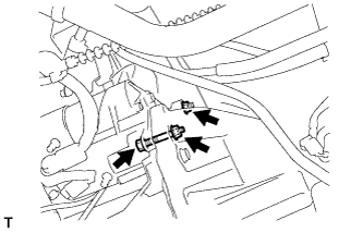
REMOVE SPEED SENSOR FRONT LH (w/ ABS)
-
Remove the 2 bolts, and separate the speed sensor from the steering knuckle.
Note
-
Be careful not to damage the speed sensor.
-
Prevent foreign matter from adhering to the speed sensor.
-
-
-
REMOVE SPEED SENSOR FRONT RH (w/ ABS)
Tech Tips
Use the same procedures described for the LH side.
-
REMOVE FRONT DISC BRAKE CALIPER ASSEMBLY LH
-
Remove the 2 bolts, and disconnect the brake caliper assembly.
Note
Use a wire or an equivalent to keep the brake caliper from hanging down by the flexible hose.
-
-
REMOVE FRONT DISC BRAKE CALIPER ASSEMBLY RH
Tech Tips
Use the same procedures described for the LH side.
-
SEPARATE FRONT SUSPENSION ARM SUB-ASSEMBLY UPPER LH
-
Remove the cotter pin and loosen the nut.
- SST
- 09628-62011
Note
Do not remove the nut.
-
Using SST, separate the steering knuckle from the suspension upper arm and remove the nut.
Note
-
Fix the steering knuckle with a wire so that the flexible hose does not receive excessive force.
-
Do not damage the ball joint dust cover.
-
-
-
SEPARATE FRONT SUSPENSION ARM SUB-ASSEMBLY UPPER RH
Tech Tips
Use the same procedures described for the LH side.
-
SEPARATE SHOCK ABSORBER ASSEMBLY FRONT LH
-
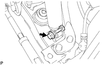
Remove the bolt and separate the front shock absorber from the front suspension lower arm.
-
-
SEPARATE SHOCK ABSORBER ASSEMBLY FRONT RH
Tech Tips
Use the same procedures described for the LH side.
-
SEPARATE CLUTCH RELEASE CYLINDER ASSEMBLY (for Manual Transmission)
-
Remove the 2 bolts and separate the clutch release cylinder
-
-
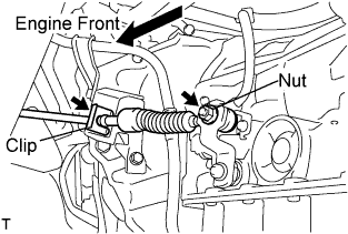
SEPARATE TRANSMISSION CONTROL CABLE ASSEMBLY (for Manual Transmission)
-
Put matchmarks on the control cable assembly and the outer lever.
-
Remove the 2 nuts and separate the transmission control cable from the outer lever.
-
Using a screwdriver, disengage the claws of the 2 clips.
-
Remove the transmission control cable and 2 clips from the transmission control cable bracket No.1.
-
-
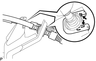
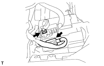
REMOVE TRANSMISSION OIL LEVEL GAUGE SUB-ASSEMBLY (for Automatic Transmission)
-
Remove the transmission oil level gauge sub-assembly from the transmission oil filler tube.
-
-
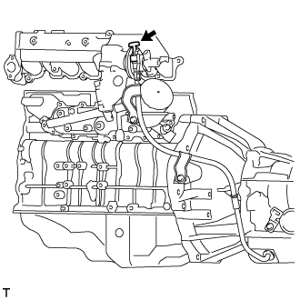
REMOVE TRANSMISSION OIL FILLER TUBE SUB-ASSEMBLY (for Automatic Transmission)
-
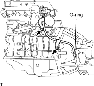
Remove the 2 bolts transmission oil filler tube sub-assembly.
-
Remove the O-ring from the oil filler tube sub-assembly.
-
-
DISCONNECT TRANSMISSION CONTROL CABLE ASSEMBLY (for Automatic Transmission)
-
Remove the nut and disconnect transmission control cable assembly from the transmission control shaft lever assembly.
-
Remove the clip and disconnect the transmission control cable assembly from the transmission control bracket.
-
-
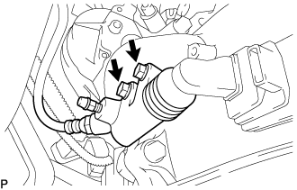
DISCONNECT OIL COOLER TUBE (for Automatic Transmission)
-
Remove each clamp and disconnect the oil cooler inlet tube and oil cooler outlet tube from the oil cooler.
-
-
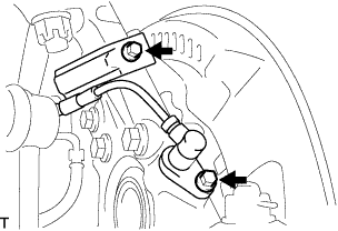
SEPARATE STEERING TORQUE SHAFT ASSEMBLY
-
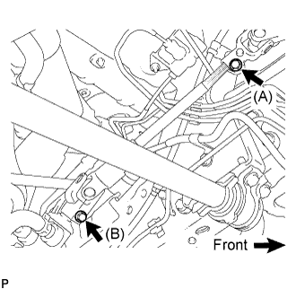
Loosen bolt (A) and remove bolt (B), then slide the steering torque shaft assembly.
Tech Tips
-
Do not remove bolt (A).
-
Do not disconnect the steering torque shaft assembly from the power steering link assembly.
-
-
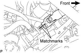
Put matchmarks on the steering torque shaft assembly and the power steering link assembly.
-
Separate the steering torque shaft assembly from the power steering link assembly.
-
-
REMOVE ENGINE ASSEMBLY WITH TRANSMISSION
-
Using the engine lifter, hold the engine assembly and separate the rear engine mount.
-
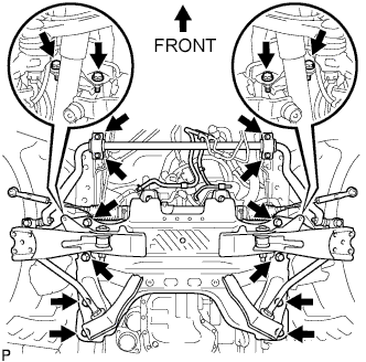
Remove the stabilizer brackets and 16 bolts of the front suspension cross member.
-
Remove the engine assembly w/ transmission out of the vehicle slowly and carefully.
-
-
REMOVE STARTER ASSEMBLY (for 2.0 kW Type)
-
for Wide Body:
Remove the bolt, then remove the ground cable.
-
Open the terminal cap.
-
Remove the nut and disconnect the wire harness from terminal 30.
-
Disconnect the terminal 50 connector from the starter assembly.
-
Remove the bolt and 2 nuts, then remove the starter.
-
-
REMOVE STARTER ASSEMBLY (for 2.2 kW Type)
-
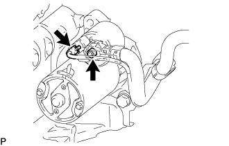
Remove the No. 2 terminal cap.
-
Disconnect the starter connector.
-
Remove the nut and disconnect the starter wire.
-
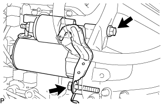
Remove the 2 bolts and disconnect the wiring harness clamp bracket.
-
Remove the stater assembly.
-
-
REMOVE STARTER ASSEMBLY (for 2.7 kW Type)
-
for Wide Body:
Remove the bolt, then disconnect the ground cable.
-
Open the terminal cap.
-
Remove the nut and disconnect the wire harness from terminal 30.
-
Disconnect the terminal 50 connector from the starter assembly.
-
Remove the bolt and 2 nuts, then remove the starter.
-
-
REMOVE MANUAL TRANSMISSION UNIT ASSEMBLY (for Manual Transmission)
-
REMOVE AUTOMATIC TRANSMISSION ASSEMBLY (for Automatic Transmission)
-
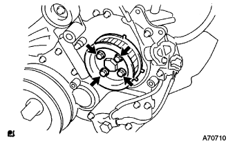
REMOVE CLUTCH COVER ASSEMBLY (for Manual Transmission)
-
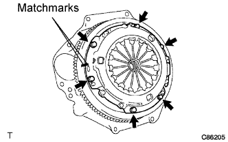
Put matchmarks on the clutch cover assembly and the flywheel sub-assembly.
-
Loosen each set bolt one turn at a time until spring tension is released.
-
Remove the set bolts, and pull off the clutch cover assembly.
Note
Do not drop the clutch disc assembly.
-
-
REMOVE CLUTCH DISC ASSEMBLY (for Manual Transmission)
Note
Keep the lining part of the clutch disc assembly, the pressure plate and surface of the flywheel sub-assembly away from oil and foreign matter.
-
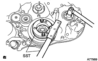
REMOVE FLYWHEEL SUB-ASSEMBLY
-
Fix the crankshaft with SST.
- SST
- 09213-58013
- 09330-00021
-
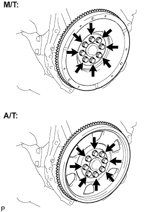
For manual transmission.
-
Remove the 8 bolts and flywheel.
-
-
For automatic transmission.
-
Remove the 8 bolts, and remove the drive plate spacer rear, drive plate and flywheel.
-
-
-
REMOVE REAR END PLATE
-
Remove the bolt and rear end plate.
-
-
REMOVE ENGINE WIRE
-
Disconnect the engine wire from the engine assembly.
-
-
INSTALL ENGINE HANGERS
-
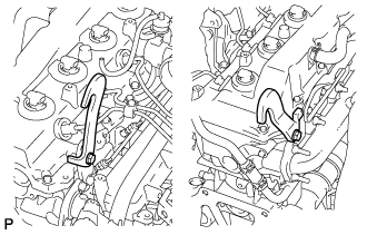
Set the engine hanger No.1 upper and engine hanger No.2 to the locations shown in the illustration.
- Torque:
- Engine hanger No.1 upper
- 25 N*m { 255 kgf*cm, 18 ft.*lbf }
- Engine hanger No.2
- 68 N*m { 693 kgf*cm, 50 ft.*lbf }
Parts name Parts No. Engine hanger No.1 upper
Bolt
12284-30020
91512-61014
Engine hanger No.2
Bolt
12282-67020
91642-81030
Note
Use a new bolt for the engine hanger.
-
-
SEPARATE OIL RESERVOIR TO PUMP HOSE NO.1
-
Remove the clip and separate the oil reservoir to pump hose No.1.
-
-
SEPARATE PRESSURE FEED TUBE ASSEMBLY
-
Remove the union bolt and separate the pressure feed tube assembly.
-
-
REMOVE FRONT SUSPENSION CROSS MEMBER
-
Hold the engine with the engine sling device and chain block.
-
Remove the 4 bolts from the front suspension cross member.
-
Remove the engine assembly by operating the engine sling device and chain block.
-
-
INSTALL ENGINE STAND
-
REMOVE VANE PUMP ASSEMBLY
-

Remove the 2 nuts and the vane pump assembly.
-
Remove the vane pump O-ring from the vane pump assembly.
-
-
REMOVE TIMING BELT COVER NO.1
-
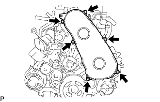
Remove the 6 bolts and timing belt No.1 cover.
-
-
REMOVE TIMING BELT
-
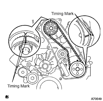
Turn the crankshaft in the clockwise direction and align the timing marks as shown in the illustration.
-
Uniformly loosen the 2 bolts, and remove the chain tensioner assembly No.1.
-
Remove the timing belt.
-
-
REMOVE FAN PULLEY
-
Remove the 4 nuts and fan pulley.
-
-
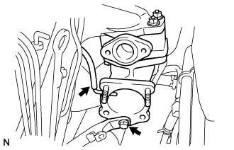
REMOVE EGR PIPE SUB-ASSEMBLY NO.1 (w/ EGR Valve)
-
Disconnect the fuel pressure sensor connector.
-
Remove the 2 bolts, 2 nuts, and the EGR pipe sub-assembly.
-
Remove the 2 gaskets.
-
-
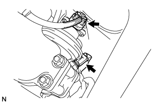
REMOVE DIESEL THROTTLE BODY ASSEMBLY
-
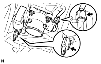
Disconnect the 2 throttle body connectors.
-
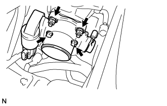
Remove the 2 bolts, 2 nuts, and the diesel throttle body assembly.
-
Remove the gasket from intake air connector.
-
-
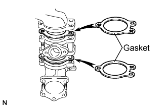
REMOVE INTAKE AIR CONNECTOR (w/o EGR Valve)
-
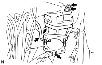
Remove the bolt, and separate the manifold stay.
-
Disconnect the vacuum hose from intake air connector.
-
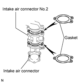
Remove the bolt, 2 nuts and the intake air connector assembly.
-
Remove the 2 gaskets and intake air connector No.2 from the intake air connector.
-
-
REMOVE ELECTRIC EGR CONTROL VALVE ASSEMBLY (w/ EGR Valve)
-
Remove the vacuum regulating valve.
-
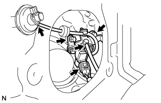
Remove the 2 vacuum hoses and the vacuum regulating valve connector.
-
Remove the 2 bolts and the vacuum regulating valve.
-
-
Remove the EGR valve assembly with the sensor.
-
Remove the bolt, and separate the manifold stay.
-
Disconnect the vacuum hose from the intake air connector.
-
Disconnect the intake air temperature sensor connector.
-
Disconnect the EGR valve position sensor connector.
-
Remove the bolt, 2 nuts and the intake air connector assembly.
-
Remove the 2 gaskets and EGR valve assembly from the intake air connector.
-
-
-
REMOVE OIL LEVEL GAUGE GUIDE
-
Remove the oil level gauge.
-
Remove the bolt and oil level gauge guide.
-
-
REMOVE INJECTION PIPE
- SST
- 09023-12701
-
Remove the injection pipe.
-
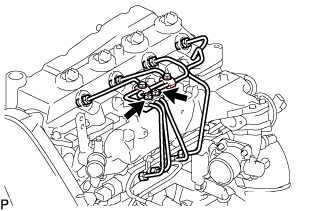
Remove the 2 nuts and injection pipe clamp No.3.
-
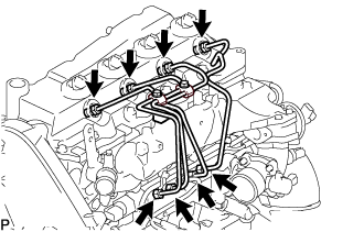
Using SST, remove the 4 injection pipes.
- SST
- 09023-12701
-
-
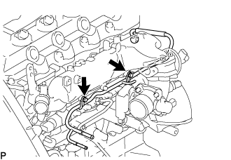
REMOVE FUEL INLET PIPE SUB-ASSEMBLY
-
Using SST, remove the fuel inlet pipe sub-assembly.
- SST
- 09023-12701
-
-
REMOVE NOZZLE LEAKAGE PIPE ASSEMBLY NO.2
-
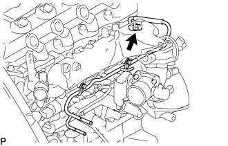
Remove the union bolt and gasket.
-
Remove the 2 bolts and the nozzle leakage pipe assembly No.2.
-
-
REMOVE INTAKE MANIFOLD
-
Remove the bolt, nut, and the manifold stay.
-
Remove the bolt, and disconnect the ground cable.
-
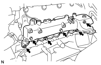
Remove the 4 bolts, 2 nuts, and intake manifold.
-
Remove the gasket from the cylinder head.
-
-
REMOVE OIL FILTER SUB-ASSEMBLY
-
Using SST, remove the oil filter.
- SST
- 09228-07501
Tech Tips
Position the drain oil container to collect the oil from the oil filter.
-
-
REMOVE COMMON RAIL ASSEMBLY
-
Disconnect the fuel pressure sensor connector from the common rail assembly.
-
Disconnect the fuel hose from the fuel pressure limiter.
-
Remove the 2 bolts and common rail assembly.
-
-
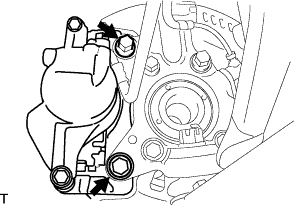
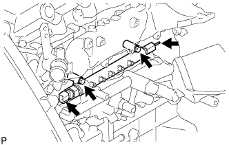
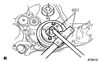
REMOVE INJECTION OR SUPPLY PUMP ASSEMBLY
-
Remove the 4 bolts.
-
Remove the camshaft timing pulley flange No.2 and pump drive shaft pulley.
-
Using SST, remove the supply pump gear set nut and O-ring while holding the crankshaft pulley.
- SST
- 09213-58013
- 09330-00021
-
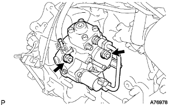
Disconnect the 2 fuel hoses.
-
Disconnect the 2 connectors and wire harness.
-
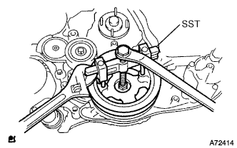
Loosen the 2 nuts as shown in the illustration.
-
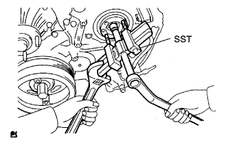
Using SST, disengage the supply pump from the supply pump gear.
- SST
- 09950-50013 ( 09951-05010, 09952-05010, 09953-05020, 09954-05021 )
-
Remove the 2 nuts and supply pump from the engine.
-
Remove the O-ring from the supply pump.
-
Remove the pulley key from the supply pump.
-
-
REMOVE OIL COOLER COVER SUB-ASSEMBLY (w/o EGR Valve)
-
Disconnect the oil pressure switch connector.
-
Disconnect the oil filter drain hoses.
-
Remove the 2 nuts, 13 bolts, oil cooler cover, and gasket.
-
-
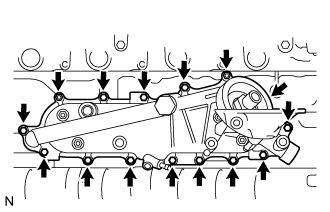
REMOVE OIL COOLER COVER SUB-ASSEMBLY (w/ EGR Valve)
-
Disconnect the oil pressure switch connector.
-
Disconnect the oil filter drain hoses.
-
Remove the 2 nuts and the vacuum transmitting pipe No.2 from the oil cooler cover.
-
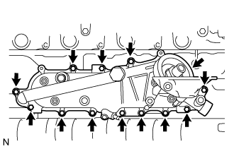
Remove the 13 bolts, oil cooler cover, and gasket.
-
-
REMOVE WATER OUTLET
-
Remove the 2 bolts, water outlet and gasket.
-
-
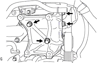
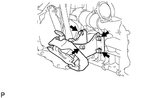
REMOVE ENGINE MOUNTING BRACKET FRONT NO.1 LH
-
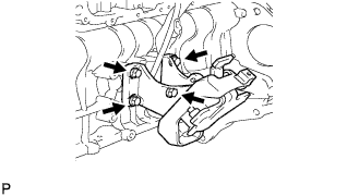
Remove the 4 bolts and the engine mounting bracket front No.1 LH.
-
-
REMOVE GLOW PLUG NO.1 CONNECTOR
-
Remove the 4 grommets.
-
Remove the 4 nuts and glow plug No.1 connectors.
-
-
REMOVE GLOW PLUG
-
Using a deep socket wrench (12 mm), remove the 4 glow plugs.
-
-
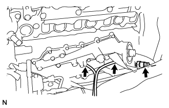
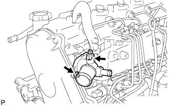
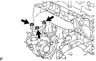
REMOVE WATER INLET
-
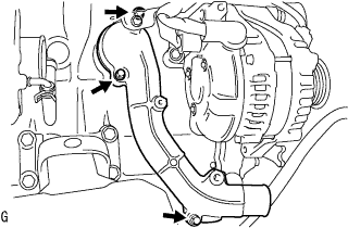
Remove the 3 bolts and water inlet.
-
-
REMOVE THERMOSTAT
-
Remove thermostat and gasket.
-
-
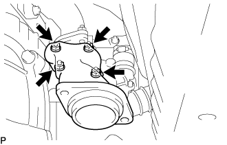
REMOVE COMPRESSOR BRACKET (w/ Air Conditioning System)
-
Remove the 4 bolts and compressor bracket.
-
-
REMOVE IDLE PULLEY ASSEMBLY (w/ Air Conditioning System)
-
Remove the bolt, washers and idle pulley assembly.
-
-
REMOVE GENERATOR BRACKET
-
Remove the 2 bolts and generator bracket.
-
-
REMOVE GENERATOR ASSEMBLY
-
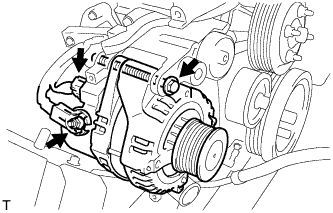
Disconnect the generator connector.
-
Remove the terminal cap.
-
Remove the nut and disconnect the wire harness from terminal B.
-
Remove the bolt and generator assembly.
-
-
REMOVE V-RIBBED BELT TENSIONER ASSEMBLY
-
Remove the 4 bolts and belt tensioner assembly.
-
-
REMOVE VENTILATION PIPE
-
Remove the bolt and ventilation pipe.
-
-
REMOVE VENTILATION HOSE HEAT INSULATOR
-
Remove the 2 bolts and ventilation hose insulator heat.
-
-
REMOVE TURBINE OUTLET ELBOW
-
Remove the 4 nuts and the turbine outlet elbow.
-
-
REMOVE TURBOCHARGER STAY
-
Remove the 3 bolts and the turbocharger stay.
-
-
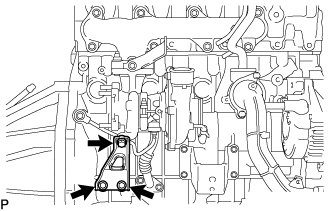
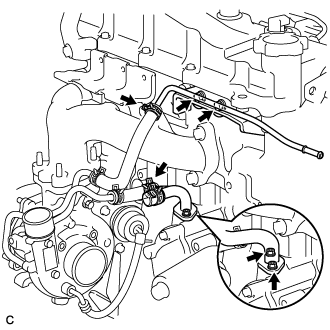
REMOVE TURBO OIL INLET PIPE SUB-ASSEMBLY
-
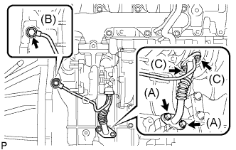
Remove the 2 bolts and the turbo oil inlet pipe from the cylinder block. (A)
Tech Tips
Place a container under the connection before disconnecting the turbo oil inlet pipe because oil in the pipe may spill out.
-
Remove the 2 bolts and the turbo oil inlet pipe from the turbocharger. (C)
-
Remove the union-bolt and gasket from the turbo oil inlet pipe. (B)
-
Remove the 2 gaskets.
-
-
REMOVE COMPRESSOR ELBOW STAY
-
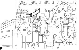
Remove the bolt and the compressor elbow stay.
-
-
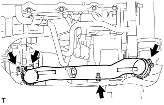
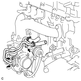
REMOVE WATER BY-PASS PIPE SUB-ASSEMBLY NO.2
-
Water cooled turbocharger (w/ heater)
-
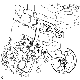
Disconnect the clip and the heater water inlet hose E.
-
Disconnect the clip and the water by-pass hose No.3.
-
Disconnect the 2 clips and the 2 water hoses.
-
Remove the 2 nuts, bolts and water bypass pipe No.2.
-
Remove the gasket.
-
-
Water cooled turbocharger (w/o heater)
-
Disconnect the clip and the water by-pass hose No.3.
-
Disconnect the 2 clips and the 2 water hoses.
-
Remove the 2 bolts and the turbo water pipe No.2.
-
Remove the 2 nuts and water by-pass pipe No.2.
-
Remove the gasket.
-
-
Air cooled turbocharger (w/o heater)
-

Remove the 2 nuts and water by-pass pipe No.2.
-
Remove the gasket.
-
-
-
REMOVE TURBO WATER PIPE SUB-ASSEMBLY NO.2 (for Water Cooled Turbocharger)
-
Remove the bolt, 2 nuts and the turbo water pipe.
-
-
REMOVE TURBOCHARGER SUB-ASSEMBLY
-
Remove the 3 bolts and the turbocharger.
-
Remove the gasket.
-
-
REMOVE EXHAUST MANIFOLD
-
Remove the 2 bolts, 6 nuts and the exhaust manifold from the cylinder head.
-
-
REMOVE ENGINE MOUNTING BRACKET FRONT NO.1 RH
-
Remove the 4 bolts and the engine mounting bracket front No.1 RH.
-
-
REMOVE TIMING BELT IDLER SUB-ASSEMBLY NO.1
-
Using a 10 mm socket hexagonal wrench, remove the bolt, plate washer and timing belt idler No.1.
-
-
REMOVE CRANKSHAFT PULLEY
-
Remove the bolt holding the crankshaft with SST.
- SST
- 09213-58013
- 09330-00021
-
Insert the service bolt.
-
Remove the crankshaft pulley with SST.
- SST
- 09950-50013 ( 09951-05010, 09952-05010, 09953-05020, 09954-05021 )
-
-
REMOVE VACUUM PUMP ASSEMBLY
-
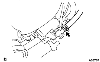
REMOVE DIESEL ENGINE WATER TEMPERATURE SENSOR
-
Using a deep-socket wrench (17 mm), remove the water temperature sensor.
-
-
REMOVE CAMSHAFT POSITION SENSOR
-
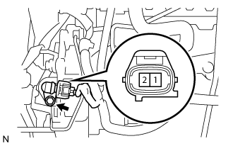
Disconnect the camshaft position sensor connector.
-
Remove the bolt and the camshaft position sensor.
-
-
REMOVE CRANKSHAFT POSITION SENSOR
-
Disconnect the crankshaft position sensor connector.
-
Separate the connector from the vacuum pipe No.1.
-
Separate the 3 wire harness clamps.
-
Remove the bolt and the crankshaft position sensor.
-
-
REMOVE ENGINE OIL LEVEL SENSOR
-
Remove the 4 bolts and engine oil level sensor.
-
-
REPLACE PARTIAL ENGINE ASSEMBLY