CYLINDER HEAD INSTALLATION

-
INSTALL CYLINDER HEAD GASKET
-
Check each piston head protrusion.
-
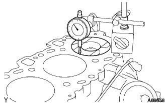
Using a dial indicator, measure the amount of each piston head protrusion between the top surfaces of each cylinder head and piston head.
Note
Set the dial indicator in an upright position to the cylinder block.
-
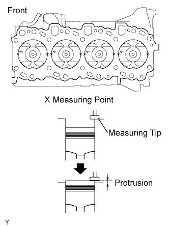
Perform the measurement at 2 places for each cylinder as shown in the illustration, making a total of 8 measurements.
-
For the piston protrusion value of each cylinder, use the average of the 2 measurements of each cylinder.
Protrusion 0.005 to 0.255 mm(0.00020 to 0.01004 in.) Tech Tips
Measurement should be done at 2 locations, right and left sides of each piston head.
-
-
Select an appropriate cylinder head gasket.
Tech Tips
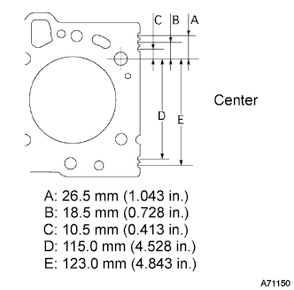
Each cylinder head gasket A to E has a unique notch position at its back-end, which helps identify an individual gasket.
-
Find the maximum value among all the measured piston head protrusion length to select an appropriate cylinder head gasket from A to E.
Piston protrusion Gasket size Piston protrusion mm (in.) A 0.005 to 0.054 (0.0002 to 0.00213) B 0.055 to 0.104 (0.00217 to 0.00409) C 0.105 to 0.154 (0.00413 to 0.00606) D 0.155 to 0.204 (0.00610 to 0.00803) E 0.205 to 0.255 (0.00807 to 0.01004) Cylinder head gasket thickness Gasket size Gasket thickness mm (in.) A 0.80 to 0.90 (0.0315 to 0.0354) B 0.85 to 0.95 (0.0335 to 0.0374) C 0.90 to 1.00 (0.0354 to 0.0394) D 0.95 to 1.05 (0.0374 to 0.0413) E 1.00 to 1.10 (0.0394 to 0.0433) -
Install the selected gasket to the cylinder block.
Note
Clean the top surface of the cylinder block and the underside of the cylinder head.
-
-
-
INSTALL CYLINDER HEAD SUB-ASSEMBLY
-
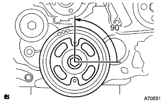
Set the crankshaft at 90° position in a counterclockwise direction from the TDC.
-
Set a new cylinder head gasket and install the cylinder head.
Tech Tips
Temporarily set a new gasket to the turbocharger before installing the cylinder head.
-
Apply a small amount of engine oil to each cylinder head bolt, screw, and washer.
-
Set the washers to the cylinder head bolts, and insert the bolts to the cylinder head.
-
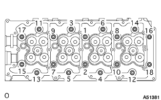
Tighten the cylinder head bolts equally in the specific order shown in the illustration in several steps, and then tighten them with the specified torque completely.
- Torque:
- 85 N*m { 867 kgf*cm, 63 ft.*lbf }
-
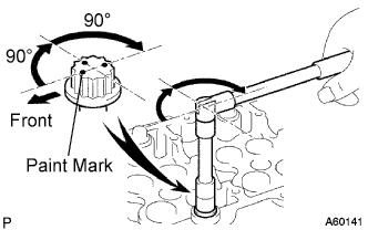
Put a paint mark on the top surface of the cylinder bolt head in the engine front direction.
-
Tighten each cylinder head bolt by 90°.
Tech Tips
The cylinder head bolts must be tightened in the specified order.
-
Tighten the bolts by additional 90°.
-
Make sure that all the paint marks come toward the opposite side to the engine front.
-
-
INSTALL CAMSHAFT
-
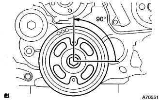
Set the crankshaft to 90° position from the TDC/compression.
-
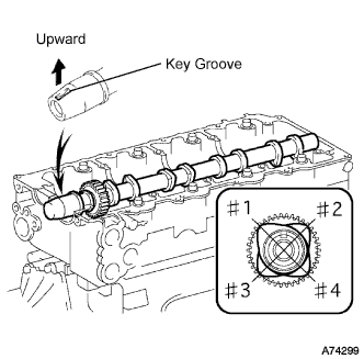
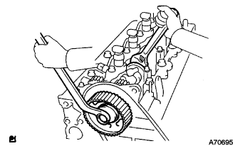
Place the camshaft to the cylinder head as shown in the illustration.
Note
Apply engine oil to the cams, thrusts and gears of the camshaft as well as on the journal of the cylinder head.
-
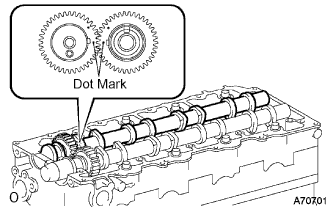
Align the dot marks of the camshaft and No.2 camshaft by meshing the both gears before placing the No.2 camshaft.
-
Remove old packing (FIPG) from the camshaft bearing cap.
-
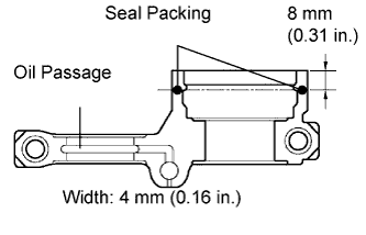
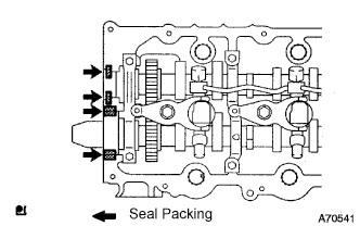
Apply seal packing to the specific places shown in the illustration.
Seal packing Toyota Genuine Seal Packing Black, Three Bond 1207B or equivalent Thickness 1 mm (0.04 in.) Note
-
Be careful not to adhere FIPG to the oil passage of the bearing cap.
-
After applying FIPG, install the camshaft bearing cap within 3 minutes and then tighten its bolts within 15 minutes.
-
Do not start the engine 2 hours after the installation.
-
-
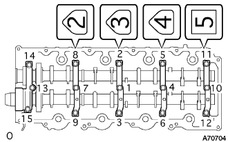
Install the camshaft bearing cap as shown in the illustration.
-
Tighten the 15 bolts for the camshaft bearing cap in the specified order shown in the illustration.
- Torque:
- 19 N*m { 194 kgf*cm, 14 ft.*lbf }
-
Adjust and inspect valve clearance.
-
Fix the timing belt cover No.2 with the 4 bolts and nuts.
- Torque:
- 10 N*m { 102 kgf*cm, 7 ft.*lbf }
-
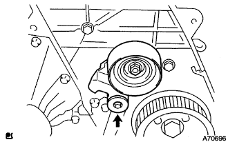
Tighten the bolt for the camshaft timing pulley while holding the camshaft with a monkey wrench.
- Torque:
- 98 N*m { 1,000 kgf*cm, 72 ft.*lbf }
-
Adjust and inspect the valve clearance. Click here
-
Remove the camshaft timing pulley and timing belt cover No.2.
-
-
-
INSTALL CAMSHAFT SETTING OIL SEAL
-
Apply a bit of MP grease to a new oil seal's lip.
Note
Keep the lip clean. Do not to bring dirt and dust on that area.
-
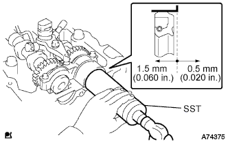
Using SST and a hammer, fit the oil seal.
- SST
- 09608-06041
Oil seal depth from flat end face 0.5 to 1.5 mm (0.020 to 0.060 in.) Note
Install the oil seal straight.
-
-
INSTALL INJECTOR ASSEMBLY

Note
It is necessary to register the injector compensation code manually in the ECM using the intelligent tester, as each injector assembly has a different injection characteristic.
-
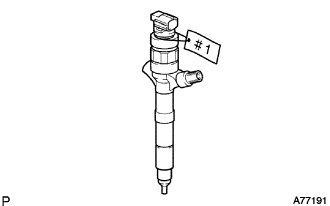
Put tags with cylinder numbers (#1 to #4) onto the new injector assembly in order to make sure of the right combinations with the right cylinders.
Standard Resistance 0.85 to 1.05 Ω at 20°C (69°F) -
Register the injector compensation code manually Click here.
-
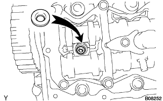
Install a new injection nozzle sheet to the cylinder head.
-
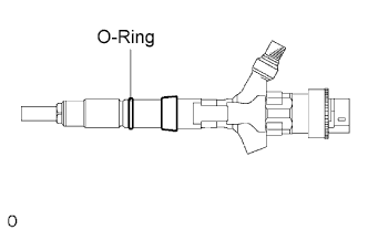
Install a new O-ring.
Tech Tips
Apply a light coat of engine oil to the O-ring.
-
Install the injector assembly to each cylinder referring to the tags with cylinder numbers (#1 to #4).
Note
If the wrong injector assembly is installed on the cylinder, rough idling or noise may occur.
-
Temporarily install the 4 injection pipes.
Note
In case of having replaced the injector, replace the injection pipe, too.
Tech Tips
Tighten the union nuts of the injection pipes by hand until them cannot turn.
-
Apply a light coat of engine oil to the 4 hollow screws and union bolt.
-
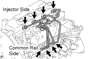
Temporarily install the nozzle leakage pipe assembly and 5 new nozzle leakage pipe gaskets and tighten the 4 hollow screws, union bolt by hand until them cannot turn.
Note
Confirm the deformation and damage the injector hollow screws, and union bolt.
-
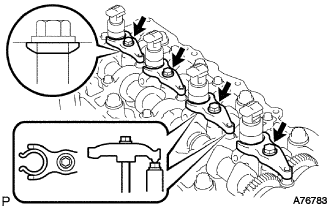
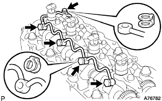
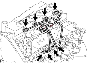
Install the 4 nozzle holder clamps and 4 new washers with the 4 bolts as show in the illustration.
-
Tighten the new washers and 4 bolts.
- Torque:
- 22 N*m { 220 kgf*cm, 16 ft.*lbf }
Note
-
Pay attention the direction of washers.
-
Clip the injector at the fork portion with a clamp which is set on the head of the cam cap bolt. At this time, check that the clamp does not hold the injector at the part where the spring is attached.
-
Temporarily torque the clamp bolts by hand until the bearing surface of the bolt touches the washer, then tighten them by the specified torque.
-
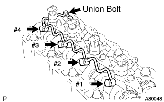
Tighten the 4 hollow screws from #1 to #4 in order.
- Torque:
- 16 N*m { 163 kgf*cm, 12 ft.*lbf }
-
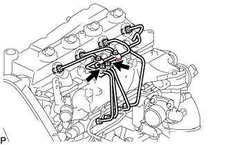
Tighten the union bolt.
- Torque:
- 13 N*m { 130 kgf*cm, 9 ft.*lbf }
Note
In case of overtightening the nozzle leakage, replace it with a new one.
-
Remove the injection pipe No.1, No.2, No.3 and No.4.
-
-
CHECK NOZZLE LEAKAGE PIPE LEAK
-
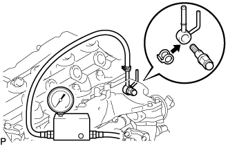
Using SST, install the nozzle leakage pipe No.2 and a new gasket.
- SST
- 09280-00010
- Torque:
- 21 N*m { 215 kgf*cm, 15 ft.*lbf }
Nozzle leakage pipe No.2 23762 - 27010 Gasket 90904 - 30012 -
Using SST (turbo charge pressure gauge), set the SST to the leakage pipe No.2 and maintain 250 kPa (2.5 kgf/cm2, 37 psi) of pressure for 60 seconds to check that there are no leaks from the nozzle leakage pipe assembly.
Note
Be sure to keep specified pressure, preventing form leakage.
Tech Tips
-
Apply a coat of engine oil to the nozzle leakage pipe assembly connection, and check that no bubbles come from the nozzle leakage pipe assembly.
-
Check that indication on the SST (turbo charger pressure gauge) does not go down while pressure is applied.
-
-
Remove the SST, nozzle leakage pipe assembly No.2.
-
-
INSTALL TIMING BELT COVER NO.2
-
Remove old seal packing (FIPG) from the timing gear case.
-
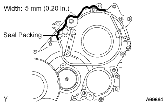
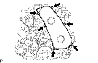
Apply seal packing to the specific places shown in the illustration.
Seal packing Toyota Genuine Seal Packing Black, Three Bond 1207B or equivalent Note
-
After applying FIPG, install the timing belt No.2 cover within 3 minutes and tighten its bolts and nuts within 15 minutes.
-
Do not start the engine 2 hours after the installation.
-
-
Fix the timing belt cover No.2 with the 4 bolts and nuts.
- Torque:
- 10 N*m { 102 kgf*cm, 7 ft.*lbf }
-
-
INSTALL TIMING BELT IDLER SUB-ASSEMBLY NO.1
-
Using a 10 mm socket hexagon wrench, install the new plate washer and timing belt idler No.1.
- Torque:
- 35 N*m { 357 kgf*cm, 26 ft.*lbf }
-
-
INSTALL CAMSHAFT TIMING PULLEY
-
Install the camshaft timing pulley.
-
Tighten the bolt for the camshaft timing pulley while holding the camshaft with a monkey wrench.
- Torque:
- 98 N*m { 1,000 kgf*cm, 72 ft.*lbf }
-
-
PISTON AND VALVE BREAKE PREVENT WORK
-
When turning the camshaft with the timing belt removed, turn the crankshaft 90° counterclockwise.
Note
When installing the timing belt, it is necessary to return the camshaft to the timing marks and then turn the crankshaft clockwise so that it aligns with the timing marks as shown in the illustration.
-
-
INSTALL TIMING BELT
-
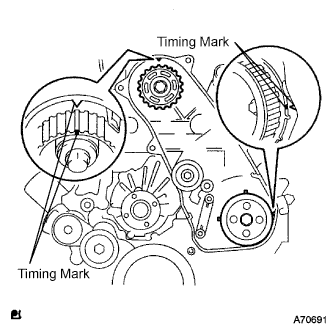
Check that the timing marks are aligned as shown in the illustration.
-
Install the timing belt to pump drive shaft pulley, camshaft timing pulley and timing belt idler No.1 in sequence.
-
Set the tensioner to the press upright.
Note
-
Do not allow the rod end to scratch and deform.
-
Press the tensioner rod in upward.
-
Protect a tip of the push rod with a rag in order to prevent damage.
-
-
Using a press, slowly apply 981 to 9,807 N (100 to 1,000 kgf, 220 to 2,205 lbf) of force to the push rod.
Note
Do not apply loads 981 to 9,807 N (100 to 1,000 kgf, 220 to 2,205 lbf) or more on the push rod.
-
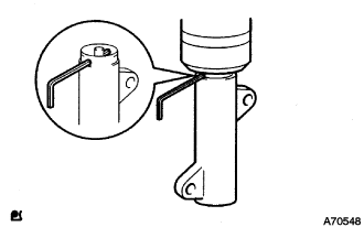
Align the holes of push rod and housing, pass a 1.27 mm hexagon wrench through the holes to keep the setting position of the push rod.
-
Temporarily install the timing belt tensioner with the 2 bolts while pushing the idler pulley toward the timing belt.
-
Tighten the 2 bolts.
- Torque:
- 13 N*m { 133 kgf*cm, 10 ft.*lbf }
Note
Uniformly tighten the 2 bolts and install the tensioner
-
Remove the 1.5 mm hexagon wrench from the tensioner.
-
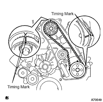
Turn the crankshaft in the clockwise direction twice, check that the timing marks are aligned as shown in the illustration.
-
-
INSTALL TIMING BELT COVER NO.1
-
Install the timing belt No.1 cover with the 6 bolts.
- Torque:
- 6.0 N*m { 61 kgf*cm, 53 in.*lbf }
-
Install the wire harness clamp.
-
-
INSTALL CYLINDER HEAD COVER SUB-ASSEMBLY
-
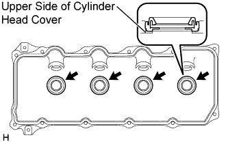
Install 4 new No. 3 cylinder head cover gaskets to the cylinder head cover as shown in the illustration.
Note
-
Do not install the gaskets at an angle.
-
Keep the lip of the gasket free from foreign materials.
-
-
Install a new cylinder head cover gasket to the cylinder head cover.
-
Remove old seal packing (FIPG) from the cylinder head.
-
Apply a seal packing to the specific places described in the illustration.
Seal packing Toyota Genuine Seal Packing Black, Three Bond 1207B or equivalent Note
-
After applying the seal packing, parts must be assembled within 3 minutes, and then tighten within 15 minutes.
-
Otherwise the material must be removed and reapplied.
-
Do not start the engine 2 hour after the installation.
-
-
Install the cylinder head cover with 10 bolts and 2 nuts.
- Torque:
- 9.0 N*m { 92 kgf*cm, 80 in.*lbf }
-
Connect the ventilation hose.
-
Install a new nozzle holder seal.
-
-
INSTALL NOZZLE LEAKAGE PIPE ASSEMBLY NO.2
-
Temporarily install the nozzle leakage pipe assembly No.2 with the 2 bolts.
-
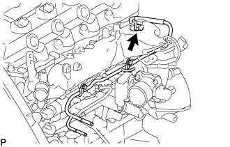
Install the check valve nozzle leakage pipe assembly No.2 and a new gasket.
- Torque:
- 21 N*m { 214 kgf*cm, 15 ft.*lbf }
-
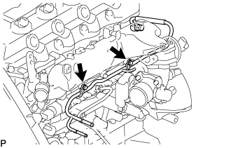
Tighten the 2 bolts.
- Torque:
- 13 N*m { 133 kgf*cm, 10 ft.*lbf }
-
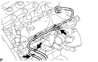
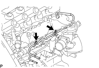
Install the 3 fuel hoses on the nozzle leakage pipe assembly No.2.
-
-
INSTALL FUEL INLET PIPE SUB-ASSEMBLY
Note
-
When replacing the fuel supply pump, common rail, cylinder block, cylinder head, cylinder head gasket, or timing gear case with a new one, replace the fuel inlet pipe.
-
Be careful not to adhere dusts, dirt or any other materials onto the joint area of the fuel inlet pipe.
-
Temporarily install the fuel inlet pipe.
-
Using SST, tighten the injection pipe on the common rail side.
- SST
- 09023-12701
- Torque:
- 32 N*m { 326 kgf*cm, 24 ft.*lbf, for use with SST }
-
Using SST, tighten the injection pipe on the supply pump side.
- SST
- 09023-12701
- Torque:
- 32 N*m { 326 kgf*cm, 24 ft.*lbf, for use with SST }
-
-
INSTALL INJECTION PIPE
- SST
- 09023-12701
Note
-
When replacing the fuel injector, common rail, or cylinder head with a new one, replace injection pipes No. 1, No. 2, No. 3, and No. 4.
-
Keep clean the joint of the injection pipe.
-
Install the injection pipes.
-
Temporarily install the 4 injection pipes.
-
Install the injection pipe clamp No.3 in 2 nuts.
- Torque:
- 5.0 N*m { 51 kgf*cm, 44 in.*lbf }
-
Fasten the union sequentially, from the injection pipe common rail to the injector, using SST.
- SST
- 09023-12701
- Torque:
- Use union nut wrench and torque wrench
- 32 N*m { 326 kgf*cm, 24 ft.*lbf }
-
-
INSTALL OIL LEVEL GAUGE GUIDE
-
Install a new O-ring to the oil level gauge guide.
-
Apply a light coat of engine oil to the O-ring.
-
Install the oil level gauge guide with the bolt.
- Torque:
- 8.0 N*m { 82 kgf*cm, 71 in.*lbf }
-
Install the oil level gauge.
-
-
INSTALL ELECTRIC EGR CONTROL VALVE ASSEMBLY (w/ EGR Valve)
-
REMOVE INTAKE AIR CONNECTOR (w/o EGR Valve)
-
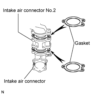
Temporarily install 2 new gaskets and intake air connector No.2 to the intake air connector.
-
Temporarily tighten the intake air connector assembly with the bolt and 2 nuts.
-
Tighten the manifold stay with the bolt.
-
Tighten the intake air connector with the bolt and 2 nuts.
-
Install the vacuum hose to the intake air connector.
-
-
INSTALL DIESEL THROTTLE BODY ASSEMBLY
-
INSTALL ENGINE SERVICE HOLE COVER NO.2
-
Install the engine service hole cover No.2 with the 3 bolts.
- Torque:
- 13 N*m { 133 kgf*cm, 10 ft.*lbf }
-
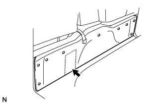
Return the carpet.
-
-
INSTALL VANE PUMP OIL RESERVOIR ASSEMBLY
-
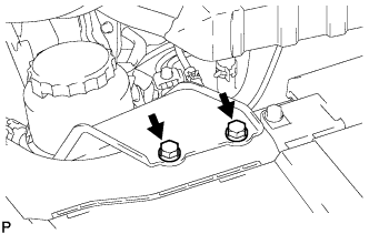
Install the vane pump oil reservoir assembly with the 2 bolts.
- Torque:
- 8.0 N*m { 82 kgf*cm, 71 in.*lbf }
-
-
CONNECT WATER BY-PASS HOSE NO.3
-
Connect the water by-pass hose No.3 with the clamp to the water by-pass pipe No.2.
-
-
CONNECT RADIATOR HOSE NO.4
-
Connect the radiator hose No.4 with the clamp to the water outlet.
-
-
CONNECT AIR HOSE NO.4
-
Connect the air hose No.4 with the clamp to the diesel throttle body.
-
-
CONNECT OIL RETURN HOSE (w/ Intercooler)
-
INSTALL TURBOCHARGER SUB-ASSEMBLY
-
INSTALL VENTILATION HOSE HEAT INSULATOR
-
Install the ventilation hose insulator heat with the 2 bolts.
- Torque:
- 12 N*m { 122 kgf*cm, 9 ft.*lbf }
-
-
INSTALL VENTILATION PIPE
-
Install the ventilation pipe with the bolt.
- Torque:
- 20 N*m { 204 kgf*cm, 15 ft.*lbf }
-
-
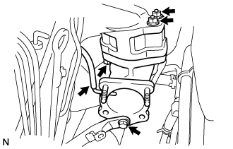
INSTALL COMPRESSOR BRACKET (w/ Air Conditioning System)
-
Temporarily install the compressor bracket with the 4 bolts.
Tech Tips
Make sure that the compressor bracket is in contact with the engine block.
-
Install the compressor bracket by tightening the 4 bolts as shown in the illustration.
- Torque:
- 45 N*m { 459 kgf*cm, 33 ft.*lbf }
-
-
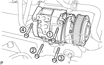
INSTALL COMPRESSOR AND MAGNETIC CLUTCH (w/ Air Conditioning System)
-
Provisionally tighten the compressor and magnetic clutch with the 4 bolts.
-
Tighten the compressor and magnetic clutch with the 4 bolts.
- Torque:
- 25 N*m { 255 kgf*cm, 18 ft.*lbf }
Note
Tighten the bolts in the order shown in the illustration to install the compressor and magnetic clutch.
-
-
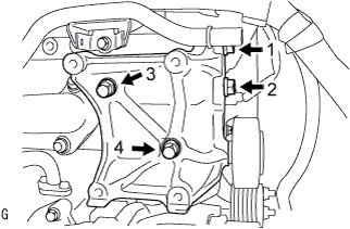
INSTALL COMPRESSOR OUTLET ELBOW
-
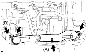
Install the compressor outlet elbow with the 2 bolts and 2 clamps.
- Torque:
- Bolt (A)
- 12 N*m { 122 kgf*cm, 9 ft.*lbf }
- Bolt (B)
- 32 N*m { 326 kgf*cm, 24 ft.*lbf }
-
-
INSTALL AIR CLEANER HOSE ASSEMBLY
-
Install the air cleaner hose assembly with the clamp.
-
-
INSTALL AIR TUBE ASSEMBLY
-
Install the air tube assembly with the 2 clamps and 2 bolts.
-
-
INSTALL FENDER APRON MUDGUARD SEAL RH
-
INSTALL EXHAUST PIPE ASSEMBLY FRONT
-
Inspect the compression spring.
-
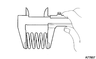
Using vernier calipers, measure the free length of the compression springs.
Minimum length 40.5mm(1.594 in.) Tech Tips
If the free length is less than the minimum, replace the compression spring.
-
-
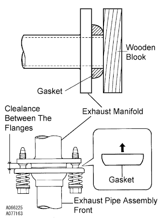
Install the gasket.
-
Fully insert a new gasket to the exhaust manifold by hand.
-
Using a wooden block, uniformly strike the gasket so that the gasket and exhaust manifold are properly fit.
Note
-
Be careful with the installation direction of the gasket.
-
Do not reuse the gasket.
-
Do not damage the gasket.
-
To ensure a proper seal, do not use the exhaust pipe assembly front to force the gasket onto the front exhaust manifold.
-
-
-
Connect the exhaust pipe support, and install the exhaust pipe assembly front and a new gasket with the 4 bolts, 2 compression springs and 2nuts.
- Torque:
- Exhaust manifold side
- 43 N*m { 438 kgf*cm, 32 ft.*lbf }
- Exhaust pipe assembly center side
- 48 N*m { 489 kgf*cm, 35 ft.*lbf }
Note
After installation, check that the clearance is almost same at any point between the flanges of the exhaust manifold and exhaust pipe assembly front .
-
-
INSTALL FAN & GENERATOR V BELT
-
Rotate the V-ribbed belt tensioner pulley clockwise, and then install the fan and generator V belt.
Note
Make sure that the fan and generator V belt is set properly on each pulley.
-
Check that the indicator mark of the V-ribbed belt tensioner Click here.
-
-
INSTALL ENGINE SERVICE HOLE SUB COVER SUB-ASSEMBLY
-
Install the engine service hole sub cover with the 5 bolts.
- Torque:
- 13 N*m { 133 kgf*cm, 10 ft.*lbf }
-
-
INSTALL FRONT DOOR SCUFF PLATE RH
-
INSTALL FRONT SEAT ASSEMBLY RH (for Hi-back Seat Type)
-
Perform the same procedure as above on the opposite side. Click here
-
-
INSTALL FRONT SEAT ASSEMBLY RH (for Low-back Seat Type)
-
Perform the same procedure as above on the opposite side. Click here
-
-
CONNECT BATTERY NEGATIVE TERMINAL
-
ADD ENGINE COOLANT
-
Firmly tighten the drain plugs.
-
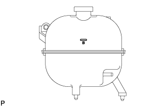
Fill the radiator reservoir assembly with engine coolant to the top of the inlet.
Standard Capacity Item Specified Condition w/o Heater 13.2 liters (13.9 US qts, 11.6 Imp. qts) w/ Front Heater 14.2 liters (15.0 US qts, 12.5 Imp. qts) w/ Front and Rear Heaters 16.2 liters (17.1 US qts, 14.3 Imp. qts) Note
Do not substitute plain water for engine coolant.
Tech Tips
-
Use of improper coolants may damage the engine cooling system.
-
Use only Toyota Super Long Life Coolant or similar high quality ethylene glycol based non-silicate, non-amine, non-nitrite, and non-borate coolant with long-life hybrid organic acid technology (coolant with long-life hybrid organic acid technology consists of a combination of low phosphates and organic acids).
-
-
Loosen the bleeder plug of the outlet housing.
-
When air is bled and the engine coolant drains out, firmly tighten the bleeder plug.
- Torque:
- 8.0 N*m { 82 kgf*cm, 71 in.*lbf }
-
Add engine coolant up to the B line mark in the radiator reservoir assembly and install the radiator reservoir cap sub-assembly.
-
Warm up the engine until the thermostat opens.
-
While the thermostat is open, circulate the engine coolant for several minutes.
Tech Tips
The thermostat open timing can be confirmed by pressing the No. 3 radiator hose by hand, and checking when the engine coolant starts to flow inside the hose.
-
-
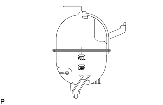
After the engine cools down, check that the engine coolant level is between the LOW and FULL level marks.
-
-
BLEED FUEL LINE
-
Move the priming pump in the upper part of the fuel filter assembly up and down, and fill the injection pump assembly and fuel system with fuel.
-
-
CHECK FUEL LEAK
-
PERFORM ACTIVE TEST
-
Connect the GTS to the DLC3.
-
Turn the ignition switch on.
-
Turn the GTS on.
-
Enter the following menus: Powertrain / Engine and ECT / Active Test.
-
Perform the Active Test.
Tester Display Test Details Control Range Diagnostic Notes Test the Fuel Leak Pressurizes common rail internal fuel pressure, and checks for fuel leaks Stop/Start
-
Fuel pressure inside common rail pressurized to specified value and engine speed increased to 2,000 rpm when ON is selected
-
Above conditions preserved while test is ON
-
-
-
-
CHECK FOR ENGINE OIL LEAKS
-
CHECK FOR ENGINE COOLANT LEAKS
CAUTION:
Do not remove the radiator cap while the engine and radiator are still hot. Pressurized, hot engine coolant and steam may be released and cause serious burns.
-
Fill the radiator with coolant and attach a radiator cap tester to the radiator.
-
Warm up the engine.
-
Using a radiator cap tester, increase the pressure inside the radiator to 137 kPa (1.4 kgf/cm2, 19.9 psi), and check that the pressure does not drop.
Tech Tips
If the pressure drops, check the hoses, radiator or water pump for leaks. If no external leaks are found, check the heater core, cylinder block and cylinder head.
-
-
CHECK EXHAUST LEAKAGE
-
INSTALL ENGINE UNDER COVER NO.1 (w/ Engine Under Cover No.1)
- Torque:
- 13 N*m { 133 kgf*cm, 10 ft.*lbf }
-
CHECK IDLE SPEED
Note
This checking procedure should be done under the following condition.
Tech Tips
-
Regarding the details about the intelligent tester, refer to its operator's manual.
-
If the intelligent tester is not available, a tachometer's tester probe can substitute for it.
-
Connect the intelligent tester to the DLC3.
-
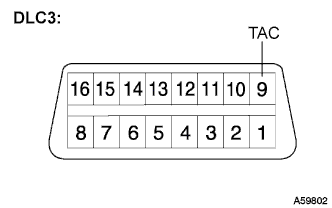
If the tester is not available, connect a tester probe of a tachometer to terminal 9 (TAC) of the DLC3 with SST.
- SST
- 09843-18030
-
Start the engine and check the idle speed.
Idle speed 700 to 800 rpm Tech Tips
If the idle speed is not as specified, check by troubleshooting in the diagnostics section.
-
In case of the tester probe of the tachometer is connected to the DLC3, disconnect the tester probe from terminal 9 of the DLC3 with SST.
-
Disconnect the intelligent tester from the DLC3.
-
-
INSPECT MAXIMUM ENGINE SPEED
Note
This checking procedure should be done under the following condition.
Tech Tips
-
Regarding the details about the intelligent tester, refer to its operator's manual.
-
If the intelligent tester is not available, a tachometer's tester probe can substitute for it.
-
Connect the intelligent tester to the DLC3.
-
If the tester is not available, connect a tester probe of a tachometer to terminal 9 (TAC) of the DLC3 with SST.
- SST
- 09843-18030
-
Start the engine.
-
Depress the accelerator pedal all the way to the limit.
-
Check the maximum speed.
Maximum speed 4500 to 4700 rpm Tech Tips
If the maximum speed is not as specified, check by troubleshooting in the diagnostics section.
-
In case of the tester probe of the tachometer is connected to the DLC3, disconnect the tester probe from terminal 9 of the DLC3 with SST.
-
Disconnect the intelligent tester from the DLC3.
-
-
CHECK FUNCTION OF THROTTLE BODY
-
Inspect the throttle control motor.
-
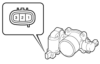
Using an ohmmeter, measure the resistance between the terminals.
Standard resistance Tester Connection Specified Condition 1 (DUTY) - Body ground Infinity
-
-
-
PERFORM INITIALIZATION