CYLINDER HEAD REMOVAL

-
SEPARATE BATTERY NEGATIVE TERMINAL
-
REMOVE ENGINE UNDER COVER NO.1 (w/ Engine Under Cover No.1)
-
DRAIN ENGINE COOLANT
CAUTION:
Do not remove the radiator reservoir cap sub-assembly while the engine and radiator are still hot. Pressurized, hot engine coolant and steam may be released and cause serious burns.
-
Loosen the radiator drain cock plug.
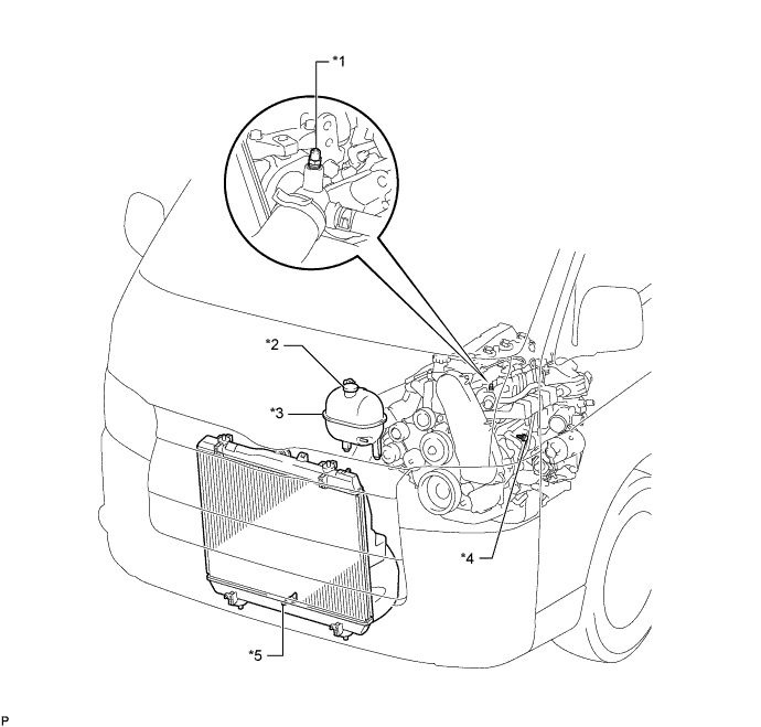
Text in Illustration *1 Bleeder Plug *2 Radiator Reservoir Cap Sub-assembly *3 Radiator Reservoir Assembly *4 Cylinder Block Drain Cock Plug *5 Radiator Drain Cock Plug - - -
Remove the radiator reservoir cap sub-assembly.
-
Loosen the cylinder block drain cock plug (on the engine oil cooler cover), and drain the engine coolant.
-
Tighten the radiator drain cock plug.
-
Tighten the cylinder block drain cock plug (on the engine oil cooler cover).
- Torque:
- 8.0 N*m { 82 kgf*cm, 71 in.*lbf }
-
-
REMOVE FRONT SEAT ASSEMBLY RH (for Hi-back Seat Type)
-
Perform the same procedure as above on the opposite side. Click here
-
-
REMOVE FRONT SEAT ASSEMBLY RH (for Low-back Seat Type)
-
Perform the same procedure as above on the opposite side. Click here
-
-
REMOVE FRONT DOOR SCUFF PLATE RH
-
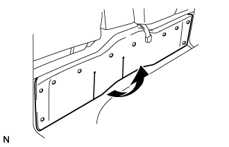
REMOVE ENGINE SERVICE HOLE SUB COVER SUB-ASSEMBLY
-
Roll up the carpet, and remove the engine service hole sub cover assembly.
-
-
REMOVE FAN & GENERATOR V BELT
-
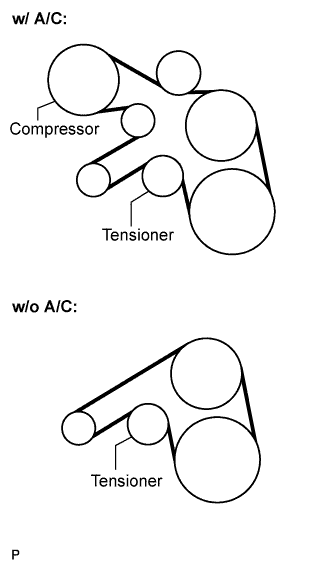
Remove the drive belt by rotating the tensioner pulley in clockwise direction to loosen its tension with the pulley set bolt of the tensioner.
-
-
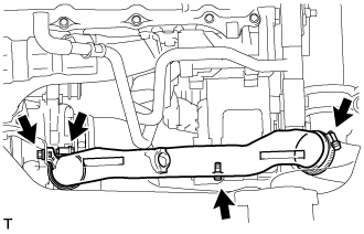
REMOVE EXHAUST PIPE ASSEMBLY FRONT
-
Remove the 4 bolts, 2 nuts, 2 compression springs. exhaust pipe assembly front and 2 gaskets.
-
Disconnect the exhaust pipe support, and remove the exhaust pipe assembly front and 2 gaskets.
-
-
REMOVE FENDER APRON MUDGUARD SEAL RH
-
REMOVE AIR TUBE ASSEMBLY
-
Remove the 2 clamps, 2 bolts and air tube assembly.
-
-
REMOVE AIR CLEANER HOSE ASSEMBLY
-
Remove the bolt and air cleaner hose assembly.
-
-
REMOVE COMPRESSOR OUTLET ELBOW
-
Remove the 2 bolts and 2 clamps, then remove the compressor outlet elbow.
-
-
SEPARATE COMPRESSOR AND MAGNETIC CLUTCH (w/ Air Conditioning System)
-
Disconnect the connector.
-
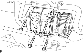
Remove the 4 bolts and compressor and magnetic clutch.
-
-
REMOVE COMPRESSOR BRACKET
-
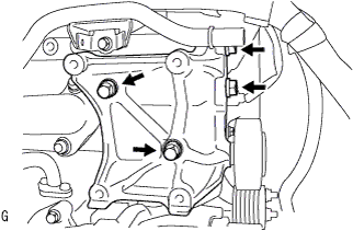
Remove the 4 bolts and compressor bracket.
-
-
REMOVE VENTILATION PIPE
-
Remove the bolt and ventilation pipe.
-
-
REMOVE VENTILATION HOSE HEAT INSULATOR
-
Remove the 2 bolts and ventilation hose insulator heat.
-
-
REMOVE TURBOCHARGER SUB-ASSEMBLY
-
DISCONNECT OIL RETURN HOSE (w/ Intercooler)
-
DISCONNECT AIR HOSE NO.4
-
Remove the clamp, and disconnect the air hose No.4 from the diesel throttle body.
-
-
DISCONNECT RADIATOR HOSE NO.4
-
Remove the clamp, and disconnect the radiator hose No.4 from the water outlet.
-
-
DISCONNECT WATER BY-PASS HOSE NO.3
-
Remove the clamp, and disconnect the water by-pass hose No.3 from the water by-pass pipe.
-
-
SEPARATE VANE PUMP OIL RESERVOIR ASSEMBLY
-
Remove the 2 bolts and vane pump oil reservoir assembly.
Note
Suspend the vane pump oil reservoir assembly with wire to prevent power steering fluid from spilling out.
-
-
REMOVE TIMING BELT COVER NO.1
-
Remove the wire harness clamp.
-
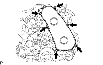
Remove the 6 bolts and timing belt cover No.1.
-
-
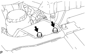
REMOVE ENGINE SERVICE HOLE COVER NO.2
-
Roll up the carpet.
-
Remove the 3 bolts and the engine service hole cover No.2.
-
-
REMOVE DIESEL THROTTLE BODY ASSEMBLY
-
REMOVE INTAKE AIR CONNECTOR (w/o EGR Valve)
-
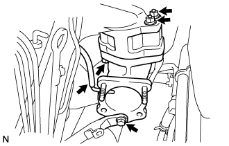
Remove the bolt, and separate the manifold stay.
-
Disconnect the vacuum hose from intake air connector.
-
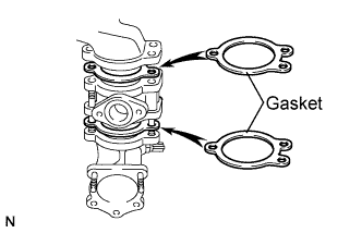
Remove the bolt, 2 nuts and the intake air connector assembly.
-
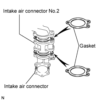
Remove the 2 gaskets and intake air connector No.2 from the intake air connector.
-
-
REMOVE ELECTRIC EGR CONTROL VALVE ASSEMBLY (w/ EGR Valve)
-
Remove the vacuum regulating valve.
-
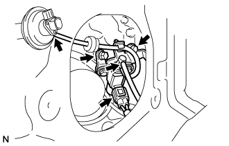
Remove the 2 vacuum hoses and the vacuum regulating valve connector.
-
Remove the 2 bolts and the vacuum regulating valve.
-
-
Remove the EGR valve assembly with the sensor.
-
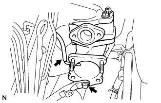
Remove the bolt, and separate the manifold stay.
-
Disconnect the vacuum hose from the intake air connector.
-
Disconnect the intake air temperature sensor connector.
-
Disconnect the EGR valve position sensor connector.
-
Remove the bolt, 2 nuts and the intake air connector assembly.
-
Remove the 2 gaskets and EGR valve assembly from the intake air connector.
-
-
-
REMOVE OIL LEVEL GAUGE GUIDE
-
Remove the oil level gauge.
-
Remove the bolt and oil level gauge guide.
-
-
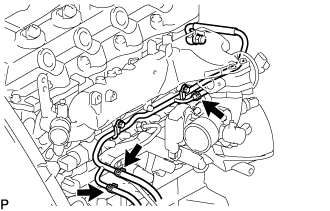
REMOVE INJECTION PIPE
- SST
- 09023-12701
-
Remove the injection pipe.
-
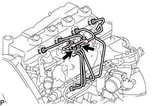
Remove the 2 nuts and injection pipe clamp No.3.
-
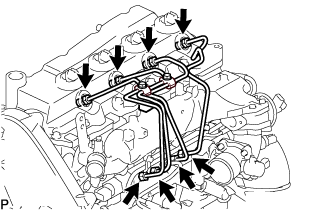
Using SST, remove the 4 injection pipes.
- SST
- 09023-12701
-
-
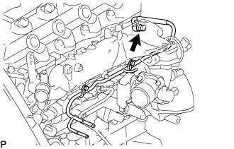
REMOVE FUEL INLET PIPE SUB-ASSEMBLY
-
Using SST, remove the fuel inlet pipe sub-assembly.
- SST
- 09023-12701
-
-
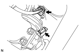
REMOVE NOZZLE LEAKAGE PIPE ASSEMBLY NO.2
-
Disconnect 3 fuel hoses from nozzle leakage pipe assembly No.2.
-
Remove the union bolt from nozzle leakage pipe No.2.
-
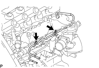
Remove the 2 bolts and nozzle leakage pipe No.2.
-
Remove the gasket from nozzle leakage pipe No.2.
-
-
REMOVE CYLINDER HEAD COVER SUB-ASSEMBLY
-
Using a small screwdriver, remove the holder seal by prying the portion between the holder seal and the cutout part of the cylinder head.
-
Disconnect the ventilation hose.
-
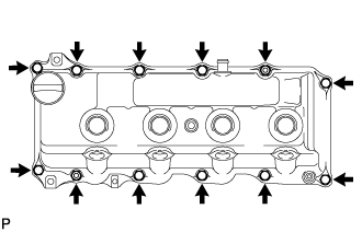
Remove the 10 bolts, 2 nuts, cylinder head cover and the cylinder head cover gasket.
Note
After removing the fuel pipe, put a plastic bag and rubber band to prevent dirt and foreign objects over the injectors inlet.
-
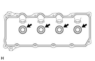
Remove the 4 No. 3 cylinder head cover gaskets from the cylinder head cover.
-
-
SET NO.1 CYLINDER TO TDC/ COMPRESSION
-
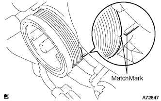
Align the matchmarks of the crankshaft pulley and timing gear case cover by rotating the crankshaft in clockwise direction.
Tech Tips
Make sure that both camnoses on the intake side and exhaust side of the cylinder No.1 face upward.
-
-
REMOVE TIMING BELT
-
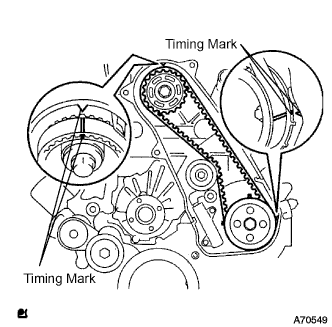
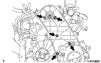
Turn the crankshaft in the clockwise direction and align the timing marks as shown in the illustration.
-
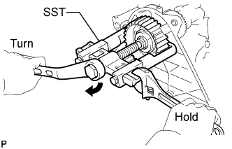
Uniformly loosen the 2 bolts, and remove the chain tensioner assembly No.1.
-
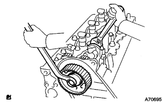
Remove the timing belt.
-
-
REMOVE CAMSHAFT TIMING PULLEY
-
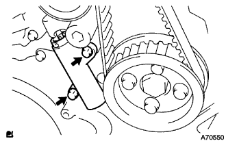
Remove the bolt for the camshaft timing pulley while holding the camshaft with a monkey wrench.
-
Using SST, remove the camshaft timing pulley.
- SST
- 09950-40011 ( 09951-04010, 09952-04010, 09953-05010, 09957-04010 )
- 09955-04150
-
-
REMOVE TIMING BELT IDLER SUB-ASSEMBLY NO.1
-
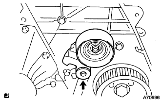
Using a 10 mm socket hexagonal wrench remove the timing belt idler No.1.
-
-
REMOVE TIMING BELT COVER NO.2
-
Remove the 4 bolts and nuts, then remove the timing belt No.2 cover.
-
-
REMOVE INJECTOR ASSEMBLY
-
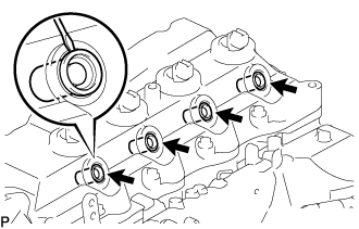
REMOVE CAMSHAFT
-
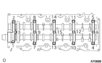
Uniformly loosen and remove the 15 camshaft bearing cap bolts in the specified order described in the illustration.
-
Remove the 5 camshaft bearing caps.
-
Pull out the oil seal.
-
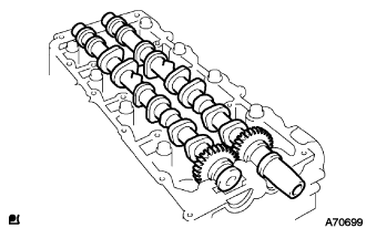
Remove the camshaft and No.2 camshaft.
Note
-
Do not pry the camshaft.
-
Do not damage the thrusts of the cylinder head.
-
-
-
REMOVE CYLINDER HEAD SUB-ASSEMBLY
-
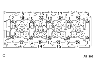
Loosen the cylinder head bolts equally and gradually in the order shown in the illustration to remove the bolt and washers.
-
-
REMOVE CYLINDER HEAD GASKET
-
INSPECT CYLINDER HEAD SET BOLT
-
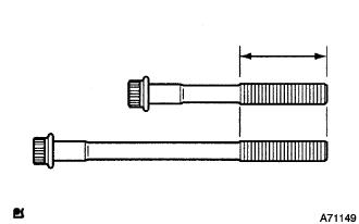
Using vernier calipers, measure the outer diameter within the specified area shown in the illustration.
Standard outer diameter 11.76 to 11.97 mm (0.463 to 0.471 in.) Minimum outer diameter 11.60 mm (0.457 in.) Tech Tips
Measure the diameter at several locations within the specified area, and replace the bolt with a new one if a result value would be less than the minimum diameter value.
-