TIMING BELT INSTALLATION
-
PISTON AND VALVE BREAKE PREVENT WORK
-
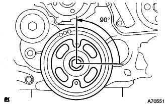
When turning the camshaft with the timing belt removed, turn the crankshaft 90° counterclockwise.
Note
When installing the timing belt, it is necessary to return the camshaft to the timing marks and then turn the crankshaft clockwise so that it aligns with the timing marks as shown in the illustration.
-
-
INSPECT TIMING BELT IDLER SUB-ASSEMBLY NO.1
-
Check that the idler pulley is turned smoothly by hand.
-
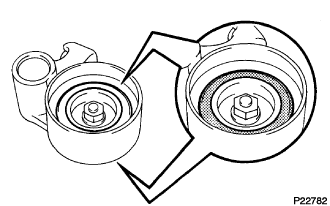
Visually check the seal portion of the idler pulley has no grease.
Note
-
Do not bend, twist or turn the timing belt inside out.
-
Do not allow the timing belt and each pulley to come into contact with oil, water or steam.
-
Before installing, be sure to clean up each pulley with a rag.
-
Do not remove the timing belt idler No.1, unless it is necessary.
-
-
-
INSPECT CHAIN TENSIONER ASSEMBLY NO.1
-
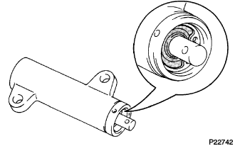
Visually check the seal portion of the tensioner for oil leakage.
Tech Tips
If there is only faint trace of oil on the seal on the push rod side, the tensioner is all right. If leakage is found, replace the tensioner.
-
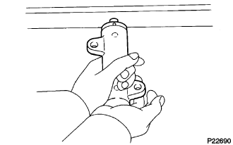
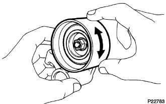
Hold the tensioner with both hands and push the push rod strongly as shown in the illustration to check that it does not move.
Tech Tips
If the push rod moves, replace the tensioner.
Note
Never hold the tensioner push rod facing downward.
-
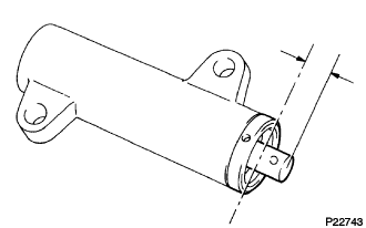
Measure the protrusion of the push rod from the housing end.
Protrusion 8.1 to 8.9 mm (0.319 to 0.350 in.) Tech Tips
If the protrusion is not as specified, replace the tensioner.
-
-
INSTALL TIMING BELT
-
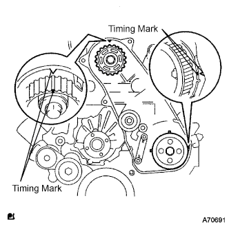
Check that the timing marks are aligned as shown in the illustration.
-
Install the timing belt to pump drive shaft pulley, camshaft timing pulley and timing belt idler No.1 in sequence.
-
Set the tensioner to the press upright.
Note
-
Do not allow the rod end to scratch and deform.
-
Press the tensioner rod in upward.
-
Protect a tip of the push rod with a rag in order to prevent damage.
-
-
Using a press, slowly apply 981 to 9,807 N (100 to 1,000 kgf, 220 to 2,205 lbf) of force to the push rod.
Note
Do not apply loads 981 to 9,807 N (100 to 1,000 kgf, 220 to 2,205 lbf) or more on the push rod.
-
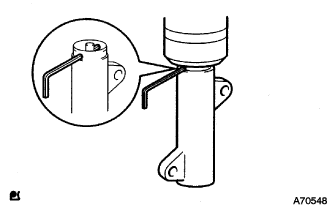
Align the holes of push rod and housing, pass a 1.27 mm hexagon wrench through the holes to keep the setting position of the push rod.
-
Temporarily install the timing belt tensioner with the 2 bolts while pushing the idler pulley toward the timing belt.
-
Tighten the 2 bolts.
- Torque:
- 13 N*m { 133 kgf*cm, 10 ft.*lbf }
Note
Uniformly tighten the 2 bolts and install the tensioner
-
Remove the 1.5 mm hexagon wrench from the tensioner.
-
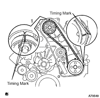
Turn the crankshaft in the clockwise direction twice, check that the timing marks are aligned as shown in the illustration.
-
-
INSTALL TIMING BELT COVER NO.1
-
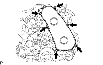
Install the timing belt No.1 cover with the 6 bolts.
- Torque:
- 6.0 N*m { 61 kgf*cm, 53 in.*lbf }
-
Install the wire harness clamp.
-
-
INSTALL FAN & GENERATOR V BELT
-
Rotate the V-ribbed belt tensioner pulley clockwise, and then install the fan and generator V belt.
Note
Make sure that the fan and generator V belt is set properly on each pulley.
-
Check that the indicator mark of the V-ribbed belt tensioner Click here.
-
-
INSTALL ENGINE SERVICE HOLE SUB COVER SUB-ASSEMBLY
-
Install the engine service hole sub cover with the 5 bolts.
- Torque:
- 13 N*m { 133 kgf*cm, 10 ft.*lbf }
-
-
INSTALL FRONT DOOR SCUFF PLATE RH
-
INSTALL FRONT SEAT ASSEMBLY RH (for Hi-back Seat Type)
-
Perform the same procedure as above on the opposite side. Click here
-
-
INSTALL FRONT SEAT ASSEMBLY RH (for Low-back Seat Type)
-
Perform the same procedure as above on the opposite side. Click here
-
-
INSTALL ENGINE UNDER COVER NO.1 (w/ Engine Under Cover No.1)
- Torque:
- 13 N*m { 133 kgf*cm, 10 ft.*lbf }