ENGINE ASSEMBLY INSTALLATION

-
INSTALL ENGINE WIRE
-
Install the engine wire to the engine assembly.
-
-
INSTALL ENGINE HANGERS
-
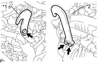
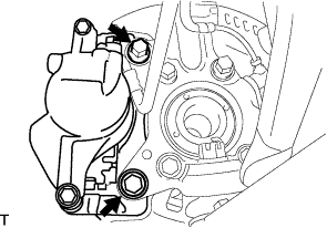
Text in Illustration *1 Upper No. 1 Engine Hanger *2 No. 2 Engine Hanger Install the upper No. 1 engine hanger and No. 2 engine hanger with the 3 bolts as shown in the illustration.
- Torque:
- for upper No. 1 engine hanger
- 29 N*m { 296 kgf*cm, 21 ft.*lbf }
- for No. 2 engine hanger
- 26 N*m { 265 kgf*cm, 19 ft.*lbf }
Note
Install the engine hangers with new bolts.
Tech Tips
Upper No. 1 Engine Hanger 12284-11010 or 12284-11020 No. 2 Engine Hanger 12282-11080 or 12282-11090 Bolt 91552-81025 and 91672-80835 -
Attach an engine sling device and hang the engine assembly with a chain block.
-
-
REMOVE ENGINE STAND
Note
-
Pay attention to the angle of the sling device as the engine assembly or engine hangers may be damaged or deformed if the angle is incorrect.
-
With the exception of installing the engine assembly to an engine stand or removing the engine assembly from an engine stand, do not perform any work on the engine assembly while it is suspended, as doing so is dangerous.
-
Attach the engine sling device and hang the engine assembly with the chain block.
-
Remove the engine assembly from the engine stand.
-
-
INSTALL FRONT ENGINE MOUNTING INSULATOR
-
Install the 2 front engine mounting insulators and 2 engine mounting stabilizers with the 2 nuts.
- Torque:
- 86 N*m { 877 kgf*cm, 63 ft.*lbf }
-
-
INSTALL FRONT ENGINE MOUNTING INSULATOR RH
-
Install the front engine mounting insulator RH to the engine mounting stabilizer with the nut.
- Torque:
- 8.0 N*m { 82 kgf*cm, 71 in.*lbf }
-
-
INSTALL FRONT SUSPENSION CROSSMEMBER SUB-ASSEMBLY
-
Install the front suspension crossmember sub-assembly to the engine assembly with the 4 bolts.
- Torque:
- 55 N*m { 561 kgf*cm, 41 ft.*lbf }
-
-
INSTALL ENGINE ASSEMBLY
-
Set an engine lifter in place.
-
Remove the engine sling device and chain block.
-
Remove the 2 bolts and 2 engine hangers.
-
Operate the engine lifter and install the engine to the vehicle.
-
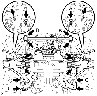
Install the engine with crossmember with the 16 bolts.
- Torque:
- for bolt A
- 39 N*m { 398 kgf*cm, 29 ft.*lbf }
- for bolt B
- 36 N*m { 367 kgf*cm, 27 ft.*lbf }
- for bolt C
- 150 N*m { 1530 kgf*cm, 111 ft.*lbf }
-
Remove the engine lifter.
-
-
INSTALL EGR PIPE INSULATOR
-
INSTALL NO. 2 ENGINE COVER
-
Install the No. 2 engine cover to the No. 1 engine hanger.
-
-
CONNECT STEERING TORQUE SHAFT ASSEMBLY
-
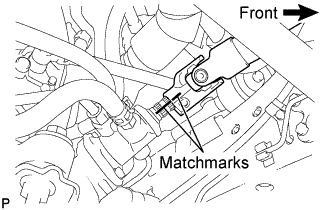
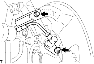
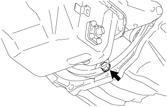
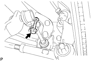
Align the matchmarks on the steering torque shaft assembly and the power steering link assembly.
-
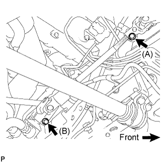
Install bolt (B) and tighten the 2 bolts.
- Torque:
- 35 N*m { 360 kgf*cm, 26 ft.*lbf }
-
-
CONNECT FRONT SHOCK ABSORBER ASSEMBLY LH
-
CONNECT FRONT SHOCK ABSORBER ASSEMBLY RH
Tech Tips
Use the same procedure described for the LH side.
-
CONNECT FRONT SUSPENSION ARM SUB-ASSEMBLY UPPER LH
-

Connect the front suspension upper arm to the steering knuckle with the nut.
- Torque:
- 113 N*m { 1,150 kgf*cm, 83 ft.*lbf }
-
Install a new cotter pin.
Note
-
If the holes for the cotter pin are not aligned, tighten the nut up to 60°.
-
Do not damage the ball joint dust cover.
-
-
-
CONNECT FRONT SUSPENSION ARM SUB-ASSEMBLY UPPER RH
Tech Tips
Use the same procedure described for the LH side.
-
CONNECT FRONT DISC BRAKE CALIPER ASSEMBLY LH
-
Install the brake caliper assembly to the steering knuckle with the 2 bolts.
- Torque:
- 123 N*m { 1,250 kgf*cm, 91 ft.*lbf }
-
-
CONNECT FRONT DISC BRAKE CALIPER ASSEMBLY RH
Tech Tips
Use the same procedure described for the LH side.
-
CONNECT FRONT SPEED SENSOR LH
-
Install the speed sensor to the steering knuckle with the 2 bolts.
- Torque:
- 8.5 N*m { 87 kgf*cm, 75 in.*lbf }
Note
-
Prevent foreign matter from adhering to the speed sensor.
-
Be careful not to damage the speed sensor.
-
Do not twist the sensor wire when installing the speed sensor.
-
-
CONNECT FRONT SPEED SENSOR RH
Tech Tips
Use the same procedure described for the LH side.
-
INSTALL REAR END PLATE
-
Install the rear end plate to the cylinder block sub-assembly with the bolt.
- Torque:
- 10 N*m { 102 kgf*cm, 7 ft.*lbf }
-
-
INSTALL FLYWHEEL SUB-ASSEMBLY
-
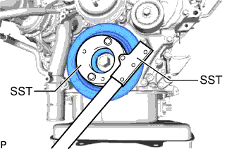
Using SST, hold the crankshaft pulley.
- SST
- 09213-58014 ( 91551-80840 )
- 09330-00021
-
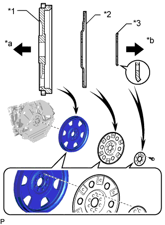
Text in Illustration *1 Flywheel Sub-assembly *2 Pump Impeller Drive Plate *3 Rear Drive Plate Spacer *a Engine Side *b Transmission Side Install the flywheel sub-assembly, the pump impeller drive plate and the rear drive plate spacer to the crankshaft with the 8 bolts.
Note
-
Align either hole in the pump impeller drive plate and either hole in the rear drive plate spacer with the knock pin of the flywheel sub-assembly, and then install the flywheel sub-assembly, the pump impeller drive plate and the rear drive plate spacer to the crankshaft.
-
Do not start the engine for at least 1 hour after installation.
Tech Tips
As the rear drive plate spacer and pump impeller drive plate are not reversible, be sure to install them in the direction shown in the illustration.
-
-
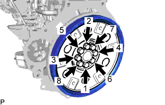
Install and uniformly tighten and tighten the 8 bolts in several steps in the sequence shown in the illustration.
- Torque:
- 178 N*m { 1815 kgf*cm, 131 ft.*lbf }
-
Install the crankshaft pulley cover to the crankshaft pulley with the 4 bolts.
- Torque:
- 21 N*m { 214 kgf*cm, 15 ft.*lbf }
-
-
INSTALL AUTOMATIC TRANSMISSION ASSEMBLY
-
INSTALL DRIVE PLATE AND TORQUE CONVERTER CLUTCH SETTING BOLT
-
Turn the crankshaft to gain access to the installation locations of the 6 drive plate and torque converter setting bolts and install each bolt while holding the crankshaft pulley bolt with a wrench.
- Torque:
- 48 N*m { 489 kgf*cm, 35 ft.*lbf }
Note
Install the black colored bolt first, and then the 5 silver colored bolts.
-
-
INSTALL PROPELLER SHAFT ASSEMBLY
-
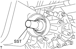
Remove the SST from the extension housing.
-
Install the propeller shaft assembly in the extension housing.
-
Align the matchmarks on the propeller shaft flange and differential flange.
-
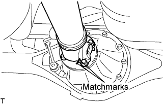
Install the propeller shaft assembly with the 4 nuts, 4 bolts and 4 washers.
- Torque:
- 74 N*m { 755 kgf*cm, 54 ft.*lbf }
-
-
CONNECT NO. 1 RADIATOR HOSE
-
Connect the No. 1 radiator hose to the water inlet, and slide the clip to secure the hose.
-
-
CONNECT NO. 2 FUEL HOSE
-
Connect the No. 2 fuel hose to the No. 3 nozzle leakage pipe assembly, and slide the clamp to secure the hose.
-
-
CONNECT NO. 1 FUEL HOSE
-
Connect the No. 1 fuel hose to the No. 2 fuel pipe, and slide the clamp to secure the hose.
-
-
CONNECT VACUUM TUBE CONNECTOR HOSE
-
Connect the vacuum tube connector hose to the No. 1 hose to hose tube, and slide the clamp to secure the hose.
-
-
INSTALL INTERCOOLER AIR TUBE
-
Install the intercooler air tube to the diesel throttle body assembly.
-
Install the air tube support bracket to the intake air tube and gas filter bracket with the 2 bolts.
- Torque:
- 6.0 N*m { 62 kgf*cm, 53 in.*lbf }
-
-
CONNECT NO. 4 AIR HOSE
-
Connect the No. 4 air hose to the No. 3 air tube.
- Torque:
- 6.0 N*m { 62 kgf*cm, 53 in.*lbf }
-
Connect the oil return hose to the No. 4 air hose, and slide the clamp to secure the hose.
-
Connect the connector to the intake air temperature sensor.
-
-
CONNECT NO. 1 COOLER REFRIGERANT SUCTION HOSE
-
Remove the attached vinyl tape from the No. 1 cooler refrigerant suction hose.
-
Sufficiently apply compressor oil to a new O-ring and the fitting surface of the cooler compressor assembly.
Compressor oil ND-OIL 8 or equivalent -
Install the O-ring to the No. 1 cooler refrigerant suction hose.
-
Connect the No. 1 cooler refrigerant suction hose to the cooler compressor with the bolt.
- Torque:
- 9.8 N*m { 100 kgf*cm, 87 in.*lbf }
-
-
CONNECT NO. 1 COOLER REFRIGERANT DISCHARGE HOSE
-
Remove the attached vinyl tape from the No. 1 cooler refrigerant discharge hose.
-
Sufficiently apply compressor oil to a new O-ring and the fitting surface of the cooler compressor assembly.
Compressor oil ND-OIL 8 or equivalent -
Install the O-ring to the No. 1 cooler refrigerant discharge hose.
-
Connect the No. 1 cooler refrigerant discharge hose to the cooler compressor with the bolt.
- Torque:
- 9.8 N*m { 100 kgf*cm, 87 in.*lbf }
-
-
CONNECT VANE PUMP ASSEMBLY
-
Connect the vane pump assembly to the generator bracket.
- Torque:
- 21 N*m { 214 kgf*cm, 15 ft.*lbf }
-
-
CONNECT VANE PUMP OIL RESERVOIR ASSEMBLY
-
Connect the vane pump oil reservoir assembly to the body with the 2 nuts.
- Torque:
- 20 N*m { 204 kgf*cm, 15 ft.*lbf }
-
-
CONNECT NO. 4 RADIATOR HOSE
-
Connect the No. 4 radiator hose to the water outlet sub-assembly, and slide the clip to secure the hose.
-
-
CONNECT WATER BY-PASS HOSE SUB-ASSEMBLY
-
Connect the water by-pass hose sub-assembly to the water by-pass pipe, and slide the clamp to secure the hose.
-
Connect the water by-pass hose sub-assembly to the water by-pass pipe assembly, and slide the clamp to secure the hose.
-
-
CONNECT NO. 1 AIR HOSE
-
Connect the No. 1 air hose to the No. 1 air tube, and slide the clamp to secure the hose.
-
-
CONNECT AIR CLEANER HOSE ASSEMBLY
-
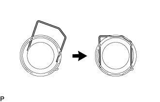
Push down the retainer of the air cleaner hose assembly as shown in the illustration.
-
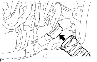
Connect the air cleaner hose assembly to the compressor inlet elbow.
Note
Check for any foreign matter on the O-ring of the air cleaner hose assembly. Clean if necessary.
-
Check that the air cleaner hose and compressor inlet elbow are securely connected by pulling on air cleaner hose assembly.
-
-
CONNECT ENGINE WIRE
-
Attach the clamp and connect the engine wire to the body.
-
Install the bolt.
- Torque:
- 9.0 N*m { 92 kgf*cm, 80 in.*lbf }
-
Connect the connector.
-
Connect the 2 connectors to the engine room main wire.
-
Attach the 2 clamps and connect the engine wire to wiring harness protector.
-
Attach the 4 claws and install the wiring harness protector cover to the wiring harness protector.
-
Install the ECM Click here.
-
-
INSTALL FRONT EXHAUST PIPE ASSEMBLY
-
INSTALL STARTER ASSEMBLY
-
INSTALL GENERATOR ASSEMBLY
-
TIGHTEN FRONT SHOCK ABSORBER ASSEMBLY LH
-
Tighten the bolt on the lower side of the front shock absorber.
- Torque:
- 105 N*m { 1,070 kgf*cm, 77 ft.*lbf }
-
-
TIGHTEN FRONT SHOCK ABSORBER ASSEMBLY RH
Tech Tips
Use the same procedure described for the LH side.
-
CONNECT CABLE TO NEGATIVE BATTERY TERMINAL
-
ADD ENGINE OIL
-
Add new engine oil.
Standard Oil Grade Item Oil Grade Oil Viscosity (SAE) w/ DPF ACEA C2
(Using engine oil other than ACEA C2 may damage catalytic converter)
- 0W-30
- 5W-30
w/o DPF G-DLD1, API CF-4, CF or ACEA B1
(You may also use API CE or CD)
- 5W-30
- 10W-30
- 15W-40
- 20W-50
Standard Capacity (w/ DPF) Item Fill Amount Drain and refill without oil filter change 6.6 liters (7.0 US qts, 5.8 Imp. qts) Drain and refill with oil filter change 6.8 liters (7.2 US qts, 6.0 Imp. qts) Dry fill 7.5 liters (7.9 US qts, 6.6 Imp. qts) Standard Capacity (w/o DPF) Item Fill Amount Drain and refill without oil filter change 6.8 liters (7.2 US qts, 6.0 Imp. qts) Drain and refill with oil filter change 7.0 liters (7.4 US qts, 6.2 Imp. qts) Dry fill 7.7 liters (8.1 US qts, 6.8 Imp. qts) -
Install the oil filler cap.
-
-
ADD ENGINE COOLANT
-
Firmly tighten the drain plugs.
-
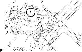
Fill the radiator reserve tank assembly with engine coolant to the top of the inlet.
Standard capacity 13.9 liters (14.6 US qts, 12.2 Imp qts) Note
Do not substitute plain water for engine coolant.
Tech Tips
-
Use of improper coolants may damage the engine cooling system.
-
Use only TOYOTA Super Long Life Coolant (SLLC) or similar high quality ethylene glycol based non-silicate, non-amine, non-nitrite, and non-borate coolant with long-life hybrid organic acid technology (coolant with long-life hybrid organic acid technology consists of a combination of low phosphates and organic acids).
-
-
Loosen the bleeder plug of the water outlet sub-assembly.
-
When air is bled and the engine coolant drains out, firmly tighten the bleeder plug.
- Torque:
- 8.0 N*m { 82 kgf*cm, 71 in.*lbf }
-
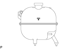
Add engine coolant up to the B line mark in the radiator reserve tank assembly and install the radiator cap sub-assembly.
-
Warm up the engine until the thermostat opens.
-
While the thermostat is open, circulate the engine coolant for several minutes.
Tech Tips
The thermostat open timing can be confirmed by pressing the No. 3 radiator hose by hand, and checking when the engine coolant starts to flow inside the hose.
-
-
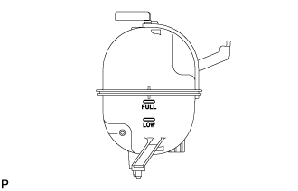
After the engine cools down, check that the engine coolant level is between the LOW and FULL line.
-
-
BLEED AIR FROM FUEL SYSTEM
-
Using the hand pump mounted on the fuel filter cap, bleed air from the fuel system. Continue pumping until the pump resistance increases.
Note
-
The maximum hand pump pumping speed is 2 strokes per second.
-
The hand pump must be pushed with a full stroke during pumping.
-
When the fuel pressure at the supply pump inlet port reaches a saturated pressure, the hand pump resistance increases.
-
If pumping is interrupted during the air bleeding process, fuel in the fuel line may return to the fuel tank. Continue pumping until the hand pump resistance increases.
-
If the hand pump resistance does not increase despite consecutively pumping 200 times or more, there may be a fuel leak between the fuel tank and fuel filter, the hand pump may be malfunctioning, or the vehicle may have run out of fuel.
-
If air bleeding using the hand pump is incomplete, the common rail pressure does not rise to the pressure range necessary for normal use and the engine cannot be started.
-
-
Check if the engine starts.
Note
-
Even if air bleeding using the hand pump has been completed, the starter may need to be cranked for 10 seconds or more to start the engine.
-
Do not crank the engine continuously for more than 20 seconds. The battery may be discharged.
-
Use a fully-charged battery.
-
When the engine can be started, proceed to the next step.
-
If the engine cannot be started, bleed air again using the hand pump until the hand pump resistance increases (refer to the procedures above). Then start the engine.
-
-
Turn the ignition switch off.
-
Connect the GTS to the DLC3.
-
Turn the ignition switch to ON and turn the GTS on.
-
Clear the DTCs Click here.
-
Start the engine.*1
-
Enter the following menus: Powertrain / Engine and ECT / Active Test / Test the Fuel Leak.*2
-
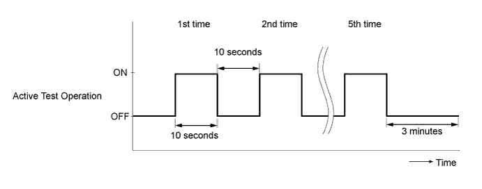
Perform the following test 5 times with on/off intervals of 10 seconds: Active Test / Test the Fuel Leak.*3
-
Allow the engine to idle for 3 minutes or more after performing the Active Test for the 5th time.
Tech Tips
When the Active Test "Test the Fuel Leak" is used to change the pump control mode, the actual fuel pressure inside the common rail drops below the target fuel pressure when the Active Test is off, but this is normal and does not indicate a pump malfunction.
-
Enter the following menus: Powertrain / Engine and ECT /Trouble Codes.
-
Read Current DTCs.
-
Clear the DTCs Click here.
Tech Tips
It is necessary to clear the DTCs as DTC P1604 or P1605 may be stored when air is bled from the fuel system after replacing or repairing fuel system parts.
-
Repeat steps *1 to *3.
-
Enter the following menus: Powertrain / Engine and ECT / Trouble Codes.
-
Read Current DTCs.
OK No DTCs are output.
-
-
CHARGE REFRIGERANT
-
Perform vacuum purging using a vacuum pump.
-
Charge with refrigerant HFC-134a (R134a).
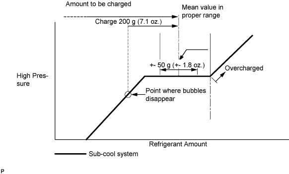
Standard Single A/C 520 to 580g (18.3 to 20.5 oz.) Dual A/C 670 to 730g (23.0 to 25.7 oz.) - SST
- 07110-58060 ( 07117-58090, 07117-78050, 07117-58070, 07117-58060, 07117-58080, 07117-88060, 07117-88070, 07117-88080 )
Note
-
Do not operate the cooler compressor before charging refrigerant as the cooler compressor does not work properly without any refrigerant, which causes the compressor to overheat.
-
Approximately 100 g (3.5 oz.) of refrigerant may need to be charged after bubbles disappear. The refrigerant amount should be checked by quantity, and not with the sight glass.
Tech Tips
Prepare a service can to recharge refrigerant if using the refrigerant gas collected with the freon collection/recycling device because the collective rate of the device is approximately 90%.
-
-
ADD AUTOMATIC TRANSMISSION FLUID
-
INSPECT FOR FUEL LEAK
Note
-
During Active Test mode, the engine speed becomes high and the combustion noise becomes loud, so pay attention.
-
During Active Test mode, the fuel pressure becomes high. Be extremely careful not to expose your eyes, hands, or body to escaping fuel.
Tech Tips
Using the GTS to perform Active Tests allow relays, VSVs, actuators and other items to be operated without removing any parts. This non-intrusive functional inspection can be very useful because intermittent operation may be discovered before parts or wiring is disturbed. Performing Active Tests early in troubleshooting is one way to save diagnostic time. Data List information can be displayed while performing Active Tests.
-
Check that there are no leaks from any part of the fuel system when the engine is stopped. If there is fuel leakage, repair or replace parts as necessary.
-
Start the engine and check that there are no leaks from any part of the fuel system. If there is fuel leakage, repair or replace parts as necessary.
-
Disconnect the return hose from the common rail assembly.
-
Start the engine and check for fuel leaks from the return pipe. If there is fuel leakage, replace the common rail assembly.
-
Perform the Active Test.
-
Connect the GTS to the DLC3.
-
Turn the ignition switch to ON.
-
Turn the GTS on.
-
Enter the following menus: Powertrain / Engine / Active Test / Test the Fuel Leak.
-
If the GTS is not available, fully depress the accelerator pedal quickly. Increase the engine speed to the maximum and maintain that speed for 2 seconds. Repeat this operation several times.
-
Check that there are no leaks from any part of the fuel system.
Tech Tips
A return pipe leakage of less than 10 cc (0.6 cu in.) per minute is acceptable.
If there is fuel leakage, repair or replace parts as necessary.
-
-
Reconnect the return hose to the common rail assembly.
-
-
INSPECT FOR OIL LEAK
-
Start the engine. Make sure that there are no oil leaks from the areas that were worked on.
-
-
INSPECT FOR COOLANT LEAK
CAUTION:
Do not remove the radiator cap sub-assembly while the engine assembly and radiator assembly are still hot. Hot, pressurized engine coolant and steam may be released and cause serious burns.
-
Fill the radiator assembly with coolant and attach a radiator cap tester to the radiator.
-
Warm up the engine.
-
Using a radiator cap tester, increase the pressure inside the radiator assembly to 137 kPa (1.4 kgf/cm2, 19.9 psi), and check that the pressure does not drop.
Tech Tips
If the pressure drops, check the hoses, radiator assembly and engine water pump assembly for leaks. If no external leaks are found, check the heater core, cylinder block sub-assembly and cylinder head sub-assembly.
-
-
INSPECT ENGINE OIL LEVEL
-
Warm up the engine, and then stop the engine and wait 5 minutes.
-
Check that the engine oil level is between the engine oil level dipstick low level mark and full level mark.
If the engine oil level is low, check for leaks and add engine oil to the full level mark.
Note
Do not fill engine oil above the full level mark.
Tech Tips
A certain amount of engine oil will be consumed while driving. In the following situations, oil consumption may increase, and engine oil may need to be refilled in between oil maintenance intervals.
-
When the engine is new, for example directly after purchasing the vehicle or after replacing the engine.
-
If low quality oil or oil of an inappropriate viscosity is used.
-
When driving at a high engine speed or with a heavy load, when towing, or when driving while accelerating or decelerating frequently.
-
When idling for a long time, or when driving frequently through heavy traffic.
When judging the amount of oil consumption, keep in mind that the oil may have become diluted, making it difficult to judge the true level accurately.
-
-
-
INSPECT AUTOMATIC TRANSMISSION FLUID LEVEL
CAUTION:
Use caution while the engine is idling and the radiator fan is operating.
Note
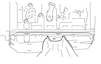
When removing the overflow plug, automatic transmission fluid may enter through the gap in the automatic transmission oil pan sub-assembly. Therefore, insert cloth between the gap in the automatic transmission oil pan sub-assembly as shown in the illustration to prevent the entry of automatic transmission fluid.
-
Lift the vehicle.
Note
Set the vehicle on a lift so that the vehicle is kept level when it is lifted up (make sure that the tilt angle from the front to rear of the vehicle is within +/-1°).
-
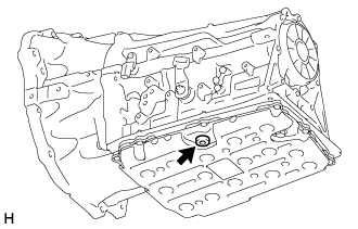
Using a 5 mm hexagon socket wrench, remove the overflow plug and gasket from the automatic transmission assembly.
CAUTION:
Be careful as the automatic transmission fluid coming out of the overflow hole is hot.
-
Check the amount of automatic transmission fluid that comes out of the overflow hole.
-
If the amount of automatic transmission fluid that comes out of the overflow hole is large, proceed to step [*1].
-
If no automatic transmission fluid comes out of the overflow hole, proceed to step [*2].
Note
If only a small amount of automatic transmission fluid (approximately 5 cc) comes out of the overflow hole, then only automatic transmission fluid remaining in the overflow tube of overflow hole has come out. This is not considered to be overflow.
-
-
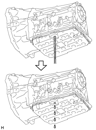
If the amount of automatic transmission fluid that comes out of the overflow hole is large, wait until the automatic transmission fluid flow slows and only drips come out. [*1]
Tech Tips
The automatic transmission fluid flow will not stop completely because the automatic transmission fluid continues to expand as its temperature increases.
-
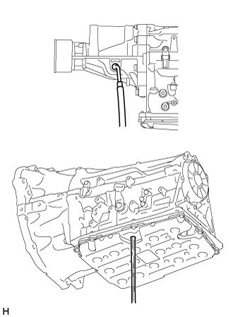
If no automatic transmission fluid comes out of the overflow hole, remove the refill plug and O-ring. Then add automatic transmission fluid to the refill hole until it flows out of the overflow hole. Wait until the automatic transmission fluid flow slows and only drips come out. [*2]
Note
-
Use Toyota Genuine ATF WS.
-
Be sure to add automatic transmission fluid slowly. If automatic transmission fluid is added quickly, the automatic transmission fluid may hit internal parts and bounce back, resulting in automatic transmission fluid coming out of the refill hole.
-
-
Wait until the automatic transmission fluid flow slows and only drips come out.
Tech Tips
The automatic transmission fluid flow will not stop completely because the automatic transmission fluid continues to expand as its temperature increases.
-
Using a 5 mm hexagon socket wrench, install a new gasket and the overflow plug to the automatic transmission assembly.
- Torque:
- 20 N*m { 204 kgf*cm, 15 ft.*lbf }
-
Install a new O-ring and the refill plug to the automatic transmission assembly.
- Torque:
- 39 N*m { 400 kgf*cm, 29 ft.*lbf }
-
Lower the vehicle.
-
Turn the ignition switch off.
Tech Tips
Turning the ignition switch off exits automatic transmission fluid temperature detection mode.
-
Disconnect the GTS from the DLC3 (when using the GTS).
-
-
INSPECT SHIFT LEVER POSITION
-
When shifting from P position only with ignition switch ON and depress the break pedal.
-
Make sure that the shifting lever moves smoothly and can be moderately operated.
-
When starting engine, make sure that the vehicle moves forward when shifting from N to D position and moves reward when shifting R position.
-
-
ADJUST SHIFT LEVER POSITION
-
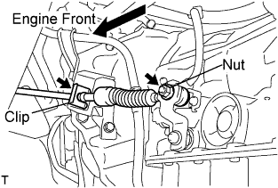
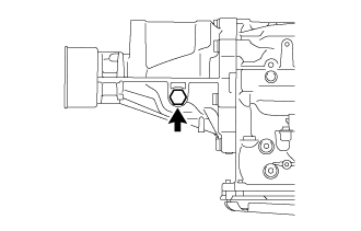
Remove a clip, nut, and disconnect between the control shaft lever to transmission control cable assembly from the control shaft lever and transmission control cable bracket No.1.
-
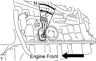
Turn the control shaft lever until stop to a clockwise direction, return the control shaft lever 2 notches to N position.
-
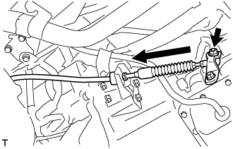
Set the shift lever to N position while holding the shift lever lightly toward the R position side and install it.
- Torque:
- 15 N*m { 150 kgf*cm, 11 ft.*lbf }
Note
Tighten the nut with it closing up cranky.
-
Inspect the operation condition and work.
-
-
INSPECT FOR EXHAUST GAS LEAK
-
If gas is leaking, tighten the areas necessary to stop the leak. Replace damaged parts as necessary.
-
-
INSPECT FOR REFRIGERANT LEAK
-
After recharging refrigerant gas, check for leakage of refrigerant gas using a halogen leak detector.
-
Carry out the test under the following conditions:
-
Stop the engine.
-
Secure good ventilation (the gas leak detector may react to volatile gases which are not refrigerant, such as evaporated gasoline and exhaust gas).
-
Repeat the test 2 or 3 times.
-
Make sure that there is some refrigerant remaining in the refrigeration system.
When the compressor is off: approx. 392 to 588 kPa (4 to 6 kgf/cm2, 57 to 85 psi)
-
-
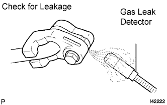
Using a gas leak detector, check for leakage of the refrigerant line.
-
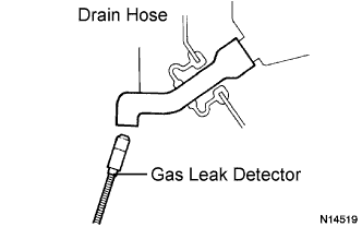
Bring the gas leak detector close to the drain hose with the detector's power off.
Tech Tips
-
After the blower motor has stopped, let the cooling unit stand for more than 15 minutes.
-
Bring the gas leak detector sensor under the drain hose.
-
When bringing the gas leak detector close to the drain hose, make sure that the gas leak detector does not react to volatile gases.
If such reaction is unavoidable, the vehicle must be lifted up.
-
-
If a gas leak is not detected on the drain hose, remove the blower motor control from the cooling unit. Insert the gas leak detector sensor into the unit and perform the test.
-
Disconnect the pressure switch connector and leave it for approximately 20 minutes. Bring the gas leak detector close to the pressure switch and perform the test.
-
-
INSTALL TRANSMISSION SERVICE HOLE COVER SUB-ASSEMBLY
-
Install the transmission service hole cover sub-assembly to the body with the 4 bolts.
- Torque:
- 7.0 N*m { 71 kgf*cm, 62 in.*lbf }
-
Return the carpet to its original position and attach the clips.
-
Connect the front center seat belt assembly RH and front center seat lap type belt assembly with the 2 bolts.
- Torque:
- 42 N*m { 428 kgf*cm, 31 ft.*lbf }
-
Install the 2 seat belt anchor covers.
-
-
INSTALL ENGINE SERVICE HOLE SUB COVER SUB-ASSEMBLY
-
Install the engine service hole sub cover sub-assembly with the 5 bolts.
- Torque:
- 13 N*m { 133 kgf*cm, 10 ft.*lbf }
-
Return the floor carpet to its original position.
-
-
INSTALL FRONT DOOR SCUFF PLATE RH
-
INSTALL FRONT SEAT ASSEMBLY RH
-
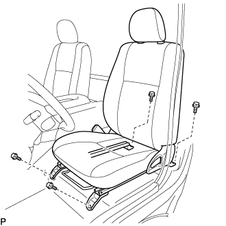
Connect the front seat inner belt assembly connector and install the front seat assembly.
-
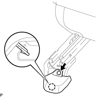
Align the front seat assembly adjuster pin with the holes in the body.
-
Move the front seat assembly to the rearmost position.
Note
Make sure that the front seat assembly is securely locked.
-
Temporarily tighten the 2 bolts on the front side of the front seat assembly.
-
Move the front seat assembly fully forward.
Note
Make sure that the front seat assembly is securely locked.
-
Temporarily tighten the 2 bolts on the rear side of the front seat assembly.
-
Move the front seat assembly to the rearmost position.
Note
Make sure that the front seat assembly is securely locked.
-
Fully tighten the 2 bolts on the front side of the front seat assembly in the order of outer and inner side.
- Torque:
- 39 N*m { 398 kgf*cm, 29 ft.*lbf }
-
Move the front seat assembly fully forward.
Note
Make sure that the front seat assembly is securely locked.
-
Fully tighten the 2 bolts on the rear side of the front seat assembly in the order of outer and inner side.
- Torque:
- 39 N*m { 398 kgf*cm, 29 ft.*lbf }
-
-
INSTALL SEAT TRACK COVER LH
-
Attach the claw and install a new seat track cover LH with a new clip.
-
-
INSPECT ENGINE IDLE SPEED
-
Warm up and stop the engine.
-
When using the GTS:
Tech Tips
-
For more information about the GTS, refer to its operator's manual.
-
If the GTS is not available, use a tachometer as a substitute.
-
Connect the GTS to the DLC3.
-
Start the engine and idle it.
-
Enter the following menus: Powertrain / Engine and ECT / Data List / Engine Speed.
Standard idle speed 650 to 750 rpm
-
-
When not using the GTS:
-
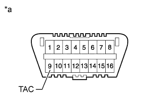
Text in Illustration *a Front view of DLC3 Connect a tester probe of a tachometer to terminal 9 (TAC) of the DLC3 with SST.
- SST
- 09843-18040
-
Start the engine and idle it.
-
-
Inspect the engine idle speed.
Standard idle speed 650 to 750 rpm Note
-
Turn all the electrical systems and A/C off.
-
When checking the idle speed, move the shift lever to neutral.
-
-
Turn the ignition switch off.
-
Disconnect the GTS or tachometer tester probe from the DLC3.
-
-
INSPECT MAXIMUM SPEED
-
Start the engine.
-
Fully depress the accelerator pedal.
-
Check the maximum engine speed.
Maximum engine speed 4450 to 4750 rpm
-
-
INSPECT AND ADJUST FRONT WHEEL ALIGNMENT
-
INSPECT ABS SPEED SENSOR SIGNAL
w/ VSC (See page Click here) w/o VSC (See page Click here)