ENGINE ASSEMBLY REMOVAL

-
PLACE FRONT WHEELS FACING STRAIGHT AHEAD
-
RECOVER REFRIGERANT FROM REFRIGERATION SYSTEM
-
Start up the engine.
-
Turn the A/C switch on.
-
Operate the cooler compressor at an engine rpm of approximately 1,000 for 5 to 6 minutes to circulate the refrigerant and collect compressor oil remaining in each component into the cooler compressor as much as possible.
-
Stop the engine.
-
Using SST, let the refrigerant gas out.
- SST
- 07110-58060 ( 07117-58080, 07117-58090, 07117-78050, 07117-88060, 07117-88070, 07117-88080 )
-
-
DISCONNECT CABLE FROM NEGATIVE BATTERY TERMINAL
-
DRAIN ENGINE COOLANT
CAUTION:
Do not remove the radiator cap sub-assembly while the engine assembly and radiator assembly are still hot. Pressurized, hot engine coolant and steam may be released and cause serious burns.
-
Connect a hose with an inside diameter of 9 mm (0.354 in.) to the radiator drain cock.
-
Loosen the radiator drain cock plug.
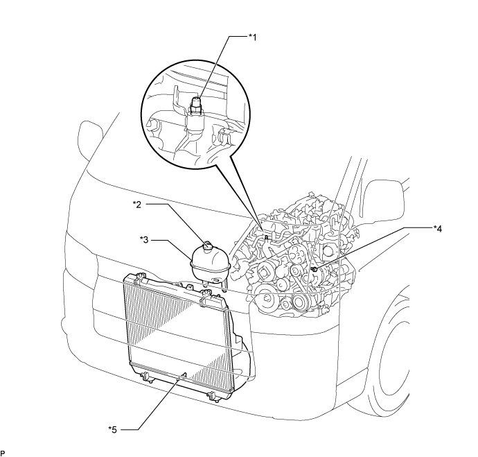
Text in Illustration *1 Bleeder Plug *2 Radiator Cap Sub-assembly *3 Radiator Reserve Tank Assembly *4 Cylinder Block Drain Cock Plug *5 Radiator Drain Cock Plug - - -
Remove the radiator cap sub-assembly.
-
Loosen the cylinder block drain cock plug, and drain the engine coolant.
-
Tighten the radiator drain cock plug.
-
Tighten the cylinder block drain cock plug.
- Torque:
- 13 N*m { 130 kgf*cm, 9 ft.*lbf }
-
Disconnect the hose from the radiator drain cock.
-
-
DRAIN ENGINE OIL
-
Remove the oil filler cap sub-assembly.
-
Remove the oil pan drain plug and gasket, and then drain the engine oil into a container.
-
Clean and install a new gasket and the oil pan drain plug.
- Torque:
- 40 N*m { 408 kgf*cm, 30 ft.*lbf }
-
-
DRAIN AUTOMATIC TRANSMISSION FLUID
-
Remove the drain plug and gasket from the automatic transmission assembly and drain the ATF.
-
Install a new gasket and the drain plug to the automatic transmission assembly.
- Torque:
- 20 N*m { 204 kgf*cm, 15 ft.*lbf }
-
-
REMOVE SEAT TRACK COVER LH
-
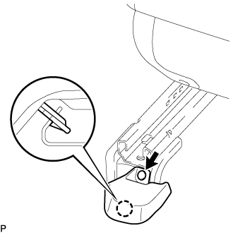
Using a clip remover, remove the clip.
-
Detach the claw and remove the seat track cover LH.
-
-
REMOVE FRONT SEAT ASSEMBLY RH
-
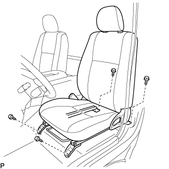
Move the front seat assembly fully forward.
-
Remove the 2 bolts on the rear side of the seat.
-
Move the front seat assembly to the rearmost position.
-
Remove the 2 bolts on the front side of the seat.
-
Move the front seat assembly to the center of the seat slide rail. Set the seatback in the upright position.
-
Disconnect the front seat inner belt assembly connector.
-
Remove the front seat assembly.
-
-
REMOVE FRONT DOOR SCUFF PLATE RH
-
REMOVE ENGINE SERVICE HOLE SUB COVER SUB-ASSEMBLY
-
Fold back the floor carpet.
-
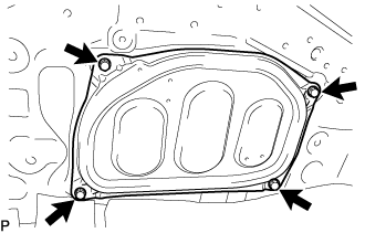
Remove the 5 bolts and engine service hole sub cover sub-assembly.
-
-
REMOVE TRANSMISSION SERVICE HOLE COVER SUB-ASSEMBLY
-
Remove the 2 seat belt anchor covers.
-
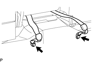
Remove the 2 bolts and disconnect the front center seat belt assembly RH and front center seat lap type belt assembly.
-
Detach the clips and fold back the carpet.
-
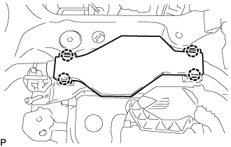
Remove the 4 bolts and transmission service hole cover sub-assembly from the body.
-
-
REMOVE GENERATOR ASSEMBLY
-
REMOVE STARTER ASSEMBLY
-
REMOVE FRONT EXHAUST PIPE ASSEMBLY
-
DISCONNECT ENGINE WIRE
-
Remove the ECM Click here.
-
Detach the 4 claw and remove the wiring harness protector cover from the wiring harness protector.
-
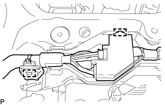
Detach the 2 clamp and disconnect engine wire from the wiring harness protector.
-
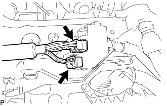
Disconnect the 2 connectors from the engine room main wire.
-
Disconnect the connector.
-
Remove the bolt.
-
Detach the clamp and disconnect the engine wire from the body.
-
-
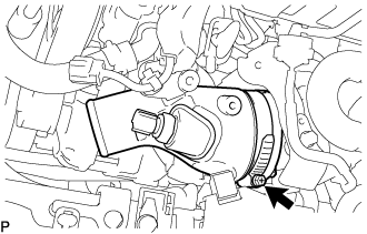
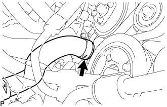
DISCONNECT AIR CLEANER HOSE ASSEMBLY
-
Lift up the retainer of air cleaner hose assembly as shown in the illustration.
-
Disconnect the air cleaner hose assembly from the compressor inlet elbow.
-
-
DISCONNECT NO. 1 AIR HOSE
-
Slide the clamp and disconnect the No. 1 air hose from the No. 1 air tube.
-
-
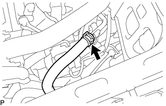
DISCONNECT WATER HOSE SUB-ASSEMBLY
-
Slide the clamp and disconnect the water hose sub-assembly from the water by-pass pipe assembly.
-
Slide the clamp and disconnect the water hose sub-assembly from the water by-pass pipe.
-
-
DISCONNECT NO. 4 RADIATOR HOSE
-
Slide the clip and disconnect the No. 4 radiator hose from the water outlet sub-assembly.
-
-
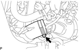
DISCONNECT VANE PUMP OIL RESERVOIR ASSEMBLY
-
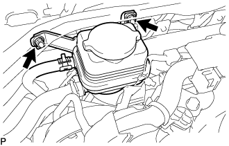
Remove the 2 nuts and disconnect the vane pump oil reservoir assembly from the body.
-
-
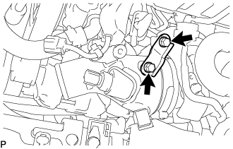
DISCONNECT VANE PUMP ASSEMBLY
-
Remove the 2 bolt and disconnect the vane pump assembly from the generator bracket.
-
-
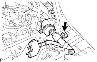
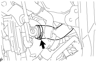
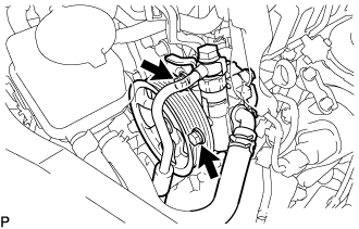
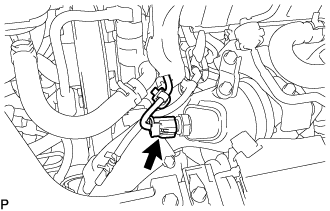
DISCONNECT NO. 1 COOLER REFRIGERANT DISCHARGE HOSE
-
Remove the bolt and disconnect the No. 1 cooler refrigerant discharge hose from the cooler compressor assembly.
-
Remove the O-ring from the No. 1 cooler refrigerant discharge hose.
Note
Seal the openings of the disconnected parts using vinyl tape to prevent moisture and foreign matter from entering them.
-
-
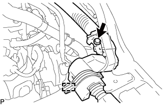
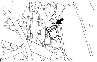
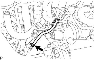
DISCONNECT NO. 1 COOLER REFRIGERANT SUCTION HOSE
-
Remove the bolt and disconnect the No. 1 cooler refrigerant suction hose from the cooler compressor assembly.
-
Remove the O-ring from the No. 1 cooler refrigerant suction hose.
Note
Seal the openings of the disconnected parts using vinyl tape to prevent moisture and foreign matter from entering them.
-
-
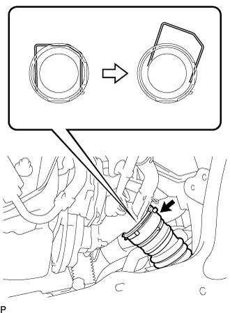
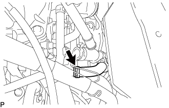
DISCONNECT NO. 4 AIR HOSE
-
Disconnect the connector from the intake air temperature sensor.
-
Slide the clamp and disconnect the oil return hose from the No. 4 air hose.
-
Disconnect the No. 4 air hose from the No. 3 air tube.
-
-
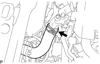
REMOVE INTERCOOLER AIR TUBE
-
Remove the 2 bolts and air tube support bracket from the intercooler air tube and gas filter bracket.
-
Remove the intercooler air tube from the diesel throttle body assembly.
-
-
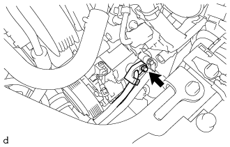
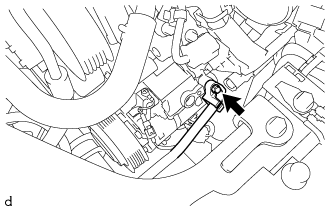
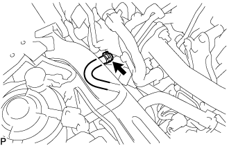
DISCONNECT VACUUM TUBE CONNECTOR HOSE
-
Slide the clamp and disconnect the vacuum tube connector hose from the No. 1 hose to hose tube.
-
-
DISCONNECT NO. 1 FUEL HOSE
-
Slide the clamp and disconnect the No. 1 fuel hose from the No. 2 fuel pipe.
-
-
DISCONNECT NO. 2 FUEL HOSE
-
Slide the clamp and disconnect the No. 2 fuel hose from the No. 3 nozzle leakage pipe assembly.
-
-
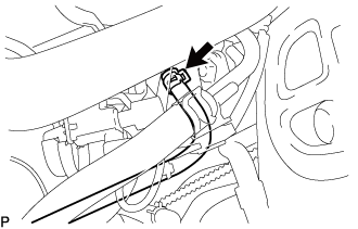
DISCONNECT NO. 1 RADIATOR HOSE
-
Slide the clip and disconnect the No. 1 radiator hose from the water inlet.
-
-
REMOVE PROPELLER SHAFT ASSEMBLY
-
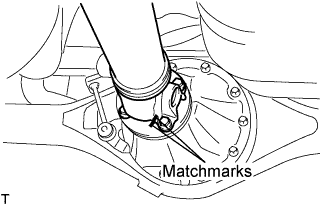
Put matchmarks on both flanges.
-
Remove the 4 nuts, bolts and washers.
Tech Tips
If the flange connection is hard to separate, temporarily tighten one nut only and evenly tap the flange with a brass bar and hammer to separate the propeller shaft assembly from the differential companion flange.
-
Remove the propeller shaft assembly.
-
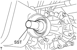
Insert SST in the transmission to prevent oil leakage.
Note
Do not damage the oil seal.
-
Use the following SST for the automatic transmission
- SST
- 09325-40010
-
Use the following SST for the manual transmission
- SST
- 09325-20010
-
-
-
REMOVE DRIVE PLATE AND TORQUE CONVERTER CLUTCH SETTING BOLT
-
Turn the crankshaft to gain access to the 6 drive plate and torque converter setting bolts and remove each bolt while holding the crankshaft pulley bolt with a wrench.
-
-
REMOVE AUTOMATIC TRANSMISSION ASSEMBLY
-
REMOVE FLYWHEEL SUB-ASSEMBLY
-
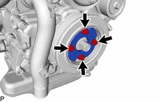
Remove the 4 bolts and crankshaft pulley cover from the crankshaft pulley.
-
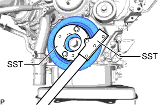
Using SST, hold the crankshaft pulley.
- SST
- 09213-58014 ( 91551-80840 )
- 09330-00021
-
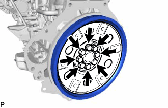
Remove the 8 bolts, rear drive plate spacer, pump impeller drive plate and flywheel sub-assembly from the crankshaft.
-
-
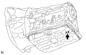
REMOVE REAR END PLATE
-
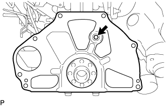
Remove the bolt and rear end plate from the cylinder block sub-assembly.
-
-
DISCONNECT FRONT SPEED SENSOR LH
-
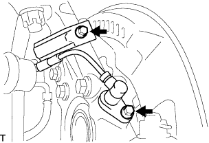
Remove the 2 bolts, and separate the speed sensor from the steering knuckle.
Note
-
Be careful not to damage the speed sensor.
-
Prevent foreign matter from adhering to the speed sensor.
-
-
-
DISCONNECT FRONT SPEED SENSOR RH
Tech Tips
Use the same procedure described for the LH side.
-
DISCONNECT FRONT DISC BRAKE CALIPER ASSEMBLY LH
-
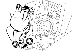
Remove the 2 bolts, and disconnect the brake caliper assembly.
Note
Use a wire or an equivalent to keep the brake caliper from hanging down by the flexible hose.
-
-
DISCONNECT FRONT DISC BRAKE CALIPER ASSEMBLY RH
Tech Tips
Use the same procedure described for the LH side.
-
DISCONNECT FRONT SUSPENSION ARM SUB-ASSEMBLY UPPER LH
-
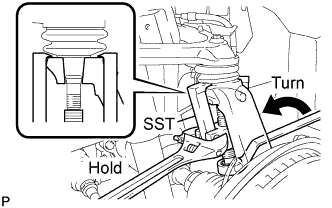
Remove the cotter pin and loosen the nut.
- SST
- 09628-62011
Note
Do not remove the nut.
-
Using SST, separate the steering knuckle from the suspension upper arm and remove the nut.
Note
-
Fix the steering knuckle with a wire so that the flexible hose does not receive excessive force.
-
Do not damage the ball joint dust cover.
-
-
-
DISCONNECT FRONT SUSPENSION ARM SUB-ASSEMBLY UPPER RH
Tech Tips
Use the same procedure described for the LH side.
-
DISCONNECT FRONT SHOCK ABSORBER ASSEMBLY LH
-
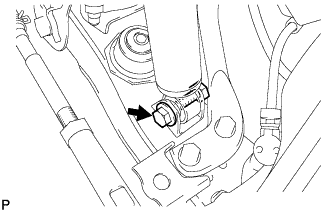
Remove the bolt and separate the front shock absorber from the front suspension lower arm.
-
-
DISCONNECT FRONT SHOCK ABSORBER ASSEMBLY RH
Tech Tips
Use the same procedure described for the LH side.
-
DISCONNECT STEERING TORQUE SHAFT ASSEMBLY
-
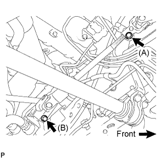
Loosen bolt (A) and remove bolt (B), then slide the steering torque shaft assembly.
Tech Tips
-
Do not remove bolt (A).
-
Do not disconnect the steering torque shaft assembly from the power steering link assembly.
-
-
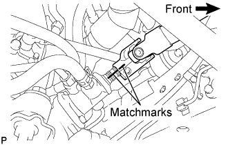
Put matchmarks on the steering torque shaft assembly and the power steering link assembly.
-
Separate the steering torque shaft assembly from the power steering link assembly.
-
-
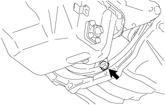
REMOVE NO. 2 ENGINE COVER
-
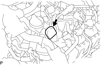
Remove the No. 2 engine cover from the No. 1 engine hanger.
-
-
REMOVE EGR PIPE INSULATOR
-
REMOVE ENGINE ASSEMBLY
-
Set an engine lifter in place.
-
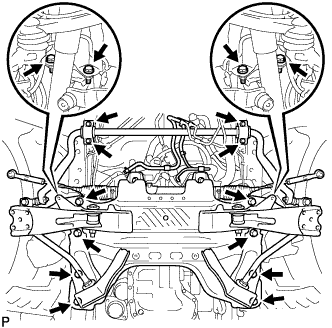
Remove the 16 bolts shown in the illustration.
-
Operate the engine lifter and slowly remove the engine from the vehicle.
-
-
INSTALL ENGINE HANGERS
-
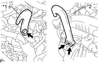
Text in Illustration *1 Upper No. 1 Engine Hanger *2 No. 2 Engine Hanger Install the upper No. 1 engine hanger and No. 2 engine hanger with the 3 bolts as shown in the illustration.
- Torque:
- for upper No. 1 engine hanger
- 29 N*m { 296 kgf*cm, 21 ft.*lbf }
- for No. 2 engine hanger
- 26 N*m { 265 kgf*cm, 19 ft.*lbf }
Note
Install the engine hangers with new bolts.
Tech Tips
Upper No. 1 Engine Hanger 12284-11010 or 12284-11020 No. 2 Engine Hanger 12282-11080 or 12282-11090 Bolt 91552-81025 and 91672-80835 -
Attach an engine sling device and hang the engine assembly with a chain block.
-
-
REMOVE FRONT SUSPENSION CROSSMEMBER SUB-ASSEMBLY
-
Remove the 4 bolts and front suspension crossmember sub-assembly from the engine assembly.
-
-
REMOVE FRONT ENGINE MOUNTING INSULATOR RH
-
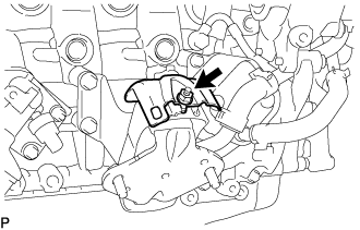
Remove the nut and front engine mounting insulator RH from the engine mounting stabilizer.
-
-
REMOVE FRONT ENGINE MOUNTING INSULATOR
-
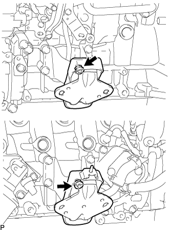
Remove the 2 nuts, 2 engine mounting stabilizers and 2 front engine mounting insulators.
-
-
INSTALL ENGINE STAND
Note
-
Pay attention to the angle of the sling device as the engine assembly or engine hangers may be damaged or deformed if the angle is incorrect.
-
With the exception of installing the engine assembly to an engine stand or removing the engine assembly from an engine stand, do not perform any work on the engine assembly while it is suspended, as doing so is dangerous.
-
Install the engine assembly to an engine stand with the bolts.
-
Remove the engine sling device and chain block.
-
Remove the 3 bolts, upper No. 1 engine hanger, and No. 2 engine hanger from the engine assembly.
-
-
REMOVE ENGINE WIRE
-
Remove the engine wire from the engine assembly.
-