REAR CRANKSHAFT OIL SEAL INSTALLATION

-
INSTALL REAR ENGINE OIL SEAL
-
Apply MP grease to the lip of a new rear engine oil seal.
Note
-
Keep the lip free of foreign matter.
-
Do not allow MP grease to contact the dust seal.
-
-
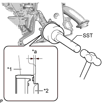
Text in Illustration *1 Rear Oil Seal Retainer *2 Rear Engine Oil Seal *a 0 to 1.0 mm (0 to 0.0394 in.) Using SST and a hammer, tap in the rear engine oil seal to the rear engine oil seal retainer edge.
- SST
- 09351-40010 ( 09351-04010, 09351-04020 )
Note
-
The acceptable depth from the top of the rear engine oil seal retainer is 0 to 1.0 mm (0 to 0.0394 in.)
-
Keep the lip free from foreign matter.
-
Do not tap the rear engine oil seal at an angle.
-
Make sure that the rear engine oil seal is properly installed.
-
-
INSTALL REAR END PLATE
-
Install the rear end plate to the cylinder block sub-assembly with the bolt.
- Torque:
- 10 N*m { 102 kgf*cm, 7 ft.*lbf }
-
-
INSTALL FLYWHEEL SUB-ASSEMBLY
-
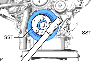
Using SST, hold the crankshaft pulley.
- SST
- 09213-58014 ( 91551-80840 )
- 09330-00021
-
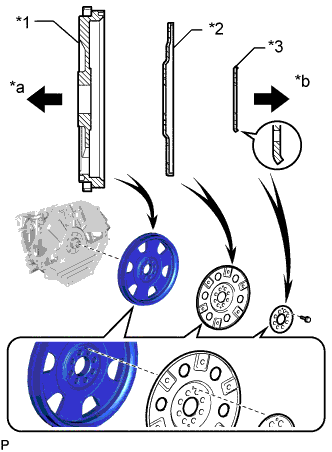
Text in Illustration *1 Flywheel Sub-assembly *2 Pump Impeller Drive Plate *3 Rear Drive Plate Spacer *a Engine Side *b Transmission Side Install the flywheel sub-assembly, the pump impeller drive plate and the rear drive plate spacer to the crankshaft with the 8 bolts.
Note
-
Align either hole in the pump impeller drive plate and either hole in the rear drive plate spacer with the knock pin of the flywheel sub-assembly, and then install the flywheel sub-assembly, the pump impeller drive plate and the rear drive plate spacer to the crankshaft.
-
Do not start the engine for at least 1 hour after installation.
Tech Tips
As the rear drive plate spacer and pump impeller drive plate are not reversible, be sure to install them in the direction shown in the illustration.
-
-
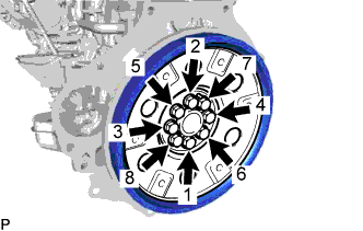
Install and uniformly tighten and tighten the 8 bolts in several steps in the sequence shown in the illustration.
- Torque:
- 178 N*m { 1815 kgf*cm, 131 ft.*lbf }
-
Install the crankshaft pulley cover to the crankshaft pulley with the 4 bolts.
- Torque:
- 21 N*m { 214 kgf*cm, 15 ft.*lbf }
-
-
INSTALL AUTOMATIC TRANSMISSION ASSEMBLY