CAMSHAFT REMOVAL

Note
-
When replacing the parts in the following chart (A), replace the No. 1 injection pipe sub-assembly, No. 2 injection pipe sub-assembly and/or fuel inlet pipe sub-assembly with new ones.
Replaced Parts (A) Pipes Requiring New Replacement Injector assembly (including shuffling the injector assemblies between the cylinders)
-
No. 1 injection pipe sub-assembly
-
No. 1 injection pipe sub-assembly
Supply pump assembly Fuel inlet pipe sub-assembly
-
Supply pump assembly
-
Common rail assembly
-
Cylinder block sub-assembly
-
Cylinder head sub-assembly
-
Cylinder head gasket
-
Timing chain case assembly
-
No. 1 injection pipe sub-assembly
-
No. 2 injection pipe sub-assembly
-
Fuel inlet pipe sub-assembly
-
-
After removing the No. 1 injection pipe sub-assembly, No. 2 injection pipe sub-assembly and/or fuel inlet pipe sub-assembly, clean them with a brush and compressed air.
-
The injector assembly is a precision instrument. Do not use the injector assembly if it is struck or dropped.
-
The supply pump assembly is a precision instrument. Do not use the supply pump assembly if it is struck or dropped.
-
Hold the supply pump assembly itself during removal and installation. Do not hold the pre-stroke control valve or fuel pipe, etc.
-
Make sure foreign matter does not enter the fuel path.
-
REMOVE ENGINE ASSEMBLY
-
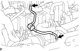
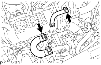
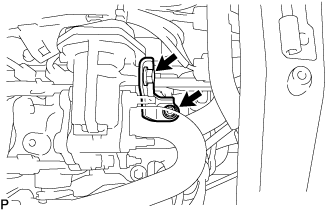
REMOVE VACUUM TUBE CONNECTOR HOSE
-
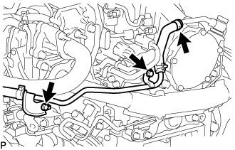
Slide the clamp and disconnect the vacuum tube connector hose from the vacuum pump assembly.
-
Remove the 2 bolts and vacuum tube connector hose from the cylinder head sub-assembly and intake manifold.
-
-
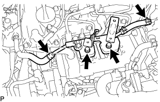
REMOVE NO. 16 WATER BY-PASS HOSE
-
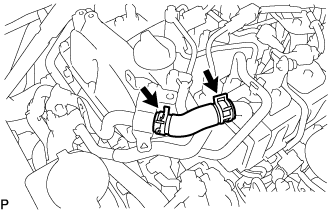
Slide the 2 clamps and remove the No. 16 water by-pass hose from the No. 1 EGR cooler and No. 2 water by-pass pipe.
-
-
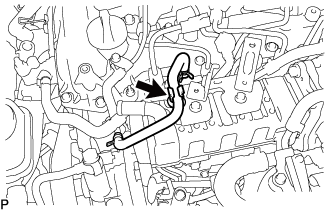
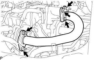
REMOVE NO. 2 WATER BY-PASS PIPE
-
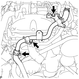
Disconnect the heater hose from the No. 2 water by-pass pipe.
-
Remove the 2 bolts and No. 2 water by-pass pipe.
-
-
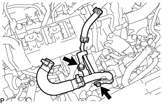
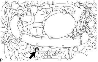
REMOVE TURBO PRESSURE SENSOR
-
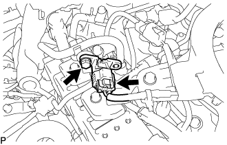
Disconnect the connector from the diesel turbo pressure sensor.
-
Remove the bolt and diesel turbo pressure sensor from the No. 3 water by-pass pipe sub-assembly.
-
-
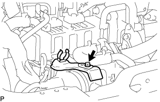
REMOVE GAS FILTER
-
Disconnect the 2 vacuum hoses from the turbo pressure sensor and intake manifold.
-
Remove the gas filter from the gas filter bracket.
-
-
REMOVE GAS FILTER BRACKET
-
Remove the bolt and gas filter bracket from the diesel throttle body assembly.
-
-
REMOVE DIESEL THROTTLE BODY ASSEMBLY
-
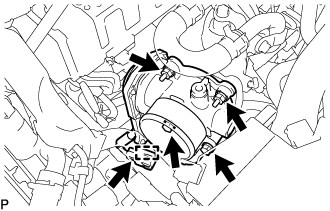
Disconnect the connector and clamp.
-
Remove the 2 bolts, 2 nuts, diesel throttle body and gasket.
-
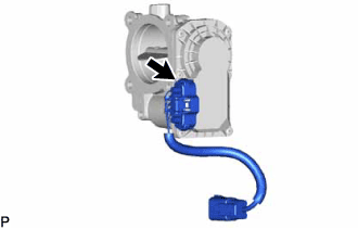
Disconnect the connector to remove the emission control valve wire from the diesel throttle body assembly.
-
-
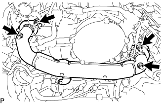
REMOVE NO. 3 WATER BY-PASS PIPE SUB-ASSEMBLY
-
Disconnect the No. 4 fuel hose from the No. 3 water by-pass pipe sub-assembly.
-
Slide the clamp and disconnect the No. 8 water by-pass hose from the No. 3 water by-pass pipe sub-assembly.
-
Slide the clamp and disconnect the No. 9 water by-pass hose from the electric EGR control valve assembly.
-
Remove the 2 bolts and No. 3 water by-pass pipe sub-assembly from the No. 1 EGR cooler.
-
-
DISCONNECT NO. 4 WATER BY-PASS PIPE SUB-ASSEMBLY
-
Slide the clamp and disconnect the No. 7 water by-pass hose from the No. 1 EGR cooler.
-
Slide the clamp and disconnect the water hose from the No. 2 EGR valve assembly.
-
Remove the 2 bolts and disconnect the No. 4 water by-pass pipe sub-assembly from the intake manifold.
-
-
REMOVE EGR VALVE BRACKET
-
Remove the bolt, nut and EGR valve bracket from the electric EGR control valve assembly and intake manifold.
-
-
REMOVE NO. 2 EGR PIPE
-
Remove the bolt, 4 nuts and No. 2 EGR pipe from the electric EGR control valve assembly and intake manifold.
-
Remove the 2 gaskets.
-
-
REMOVE NO. 1 EGR PIPE SUB-ASSEMBLY
-
Remove the bolt and disconnect the No. 1 EGR pipe sub-assembly from the vacuum transmitting pipe sub-assembly.
-
Remove the 4 nuts and the No. 1 EGR pipe sub-assembly from the exhaust manifold and EGR valve adapter.
-
Remove the 2 gaskets.
-
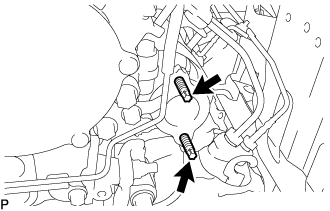
Using an E8 "TORX" socket wrench, remove the 2 stud bolts from the exhaust manifold.
-
-
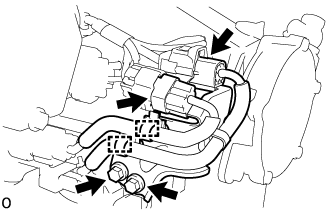
REMOVE VACUUM CONTROL VALVE SET
-
Disconnect the connector from the vacuum control valve set.
-
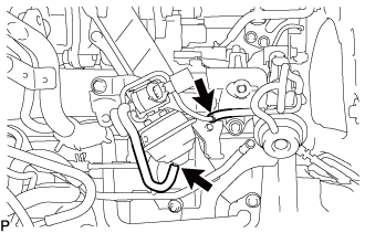
Disconnect the 2 vacuum hoses from the vacuum control valve set and No. 2 EGR valve assembly.
-
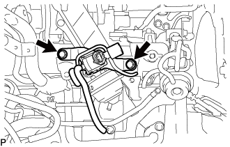
Remove the 2 bolts and vacuum control valve set from the intake manifold.
-
-
REMOVE NO. 1 EGR COOLER AND NO. 2 EGR VALVE ASSEMBLY WITH ELECTRIC EGR CONTROL VALVE ASSEMBLY
-
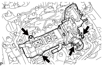
Remove the 4 bolts and No. 1 EGR cooler and No. 2 EGR valve assembly with electric EGR control valve assembly from the intake manifold.
-
-
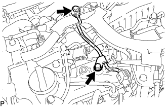
REMOVE WIRING HARNESS CLAMP BRACKET
-
Disconnect the pressure discharge valve connector from the common rail assembly.
-
Remove the bolt and wiring harness clamp bracket from the cylinder head cover sub-assembly.
-
-
REMOVE HARNESS BRACKET
-
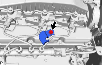
Remove the bolt and harness bracket.
-
-
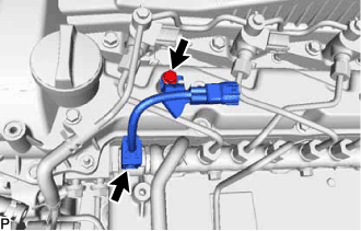
REMOVE NO. 1 FUEL PIPE
-
Remove the bolt, union bolt and gasket and disconnect the No. 1 fuel pipe from the cylinder head cover sub-assembly and exhaust fuel addition injector assembly.
-
Disconnect the No. 4 fuel pipe and remove the No. 1 fuel pipe Click here.
-
-
REMOVE NOZZLE LEAKAGE PIPE ASSEMBLY
-
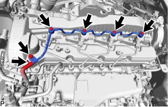
Slide the clamp and disconnect the No. 5 fuel hose from the nozzle leakage pipe assembly.
-
Remove the 4 union bolts and 4 gaskets.
-
Remove the bolt and nozzle leakage pipe assembly.
-
-
REMOVE NO. 1 INJECTION PIPE SUB-ASSEMBLY AND NO. 2 INJECTION PIPE SUB-ASSEMBLY
Note
After removing the No. 1 and No. 2 injection pipe sub-assemblies, cover the common rail assembly with electrical tape to prevent dirt or foreign objects from entering the pipe inlet. Also, protect the injector inlets with electrical tape or plastic bags.
-
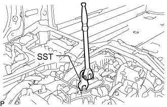
Using SST, loosen the No. 1 and No. 2 injection pipe sub-assemblies and 8 union nuts of the fuel injector assembly side and common rail assembly side.
- SST
- 09245-11010
-
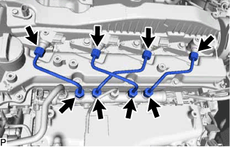
Remove the 2 No. 1 injection pipe sub-assemblies and 2 No. 2 injection pipe sub-assemblies.
Note
When removing the No. 1 injection pipe sub-assembly and No. 2 injection pipe sub-assembly, store the injector assemblies in the correct order so that they can be returned to their original locations when reassembling.
-
-
REMOVE INJECTOR ASSEMBLY
-
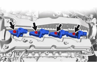
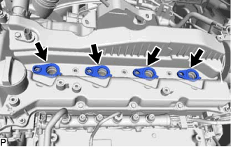
Remove the 4 nozzle holder clamp bolts, 4 washers and 4 nozzle holder clamps.
-
Remove the 4 fuel injector assemblies and 4 injection nozzle seats from the cylinder head sub-assembly.
Note
When removing the injector assembly, store the injector assemblies in the correct order so that they can be returned to their original locations when reassembling.
-
Remove the O-ring from each injector assembly.
-
-
REMOVE NOZZLE HOLDER GASKET
-
Remove the 4 nozzle holder gaskets from the cylinder head cover sub-assembly.
-
-
DISCONNECT BRACKET
-
Detach the 2 clamps and disconnect the 2 connectors from the bracket.
-
Remove the 2 bolts and disconnect the bracket from the cylinder head sub-assembly.
-
-
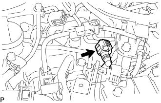
REMOVE CAMSHAFT POSITION SENSOR
-
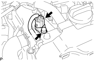
Disconnect the camshaft position sensor connector.
-
Remove the bolt and camshaft position sensor from the cylinder head cover sub-assembly.
-
-
REMOVE VACUUM PUMP ASSEMBLY
-
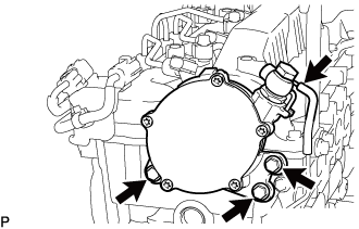
Disconnect the No. 1 vacuum transmitting hose sub-assembly from the vacuum pump assembly.
-
Remove the 3 bolts and vacuum pump assembly from the cylinder head sub-assembly.
-
Remove the 2 O-rings from the vacuum pump assembly.
-
-
REMOVE CAMSHAFT OIL SEAL RETAINER
-
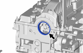
Remove the camshaft oil seal retainer from the No. 3 camshaft bearing cap and cylinder head sub-assembly.
-
-
REMOVE CYLINDER HEAD COVER SUB-ASSEMBLY
-
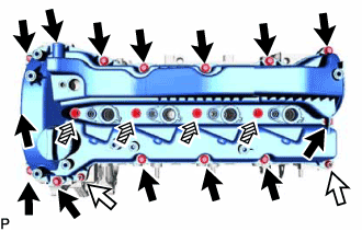
Remove the 14 bolts, 4 nozzle holder clamp seats, 2 nuts and cylinder head cover sub-assembly from the cylinder head sub-assembly.
Text in Illustration 
Bolt 
Nut 
Nozzle Holder Clamp Seat -
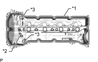
Text in Illustration *1 Cylinder Head Cover Gasket *2 No. 2 Cylinder Head Cover Gasket *3 Camshaft Bearing Cap Oil Hole Gasket Remove the cylinder head cover gasket, No. 2 cylinder head cover gasket and 2 camshaft bearing cap oil hole gaskets from the cylinder head cover sub-assembly.
-
-
SET NO. 1 CYLINDER TO TDC/COMPRESSION
-
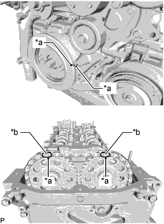
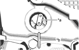
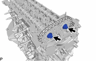
Text in Illustration *a Timing Mark *b Paint Mark Align the timing mark of the crankshaft pulley and timing chain cover by rotating the crankshaft clockwise.
-
Make sure that the timing mark of the camshaft timing sprocket is at the top.
Tech Tips
If the timing mark is not at the top, turn the crankshaft pulley 1 revolution so that the timing mark is at the top (set the No. 1 piston to TDC/ compression).
-
Place paint marks on the No. 2 chain sub-assembly.
-
-
REMOVE TIMING CHAIN GUIDE
-
Remove the bolt and timing chain guide from the cylinder head sub-assembly.
-
-
REMOVE CAMSHAFT
-
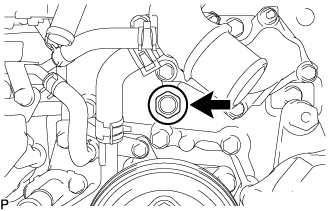
Remove the oil pump relief valve plug and gasket from timing chain cover.
-
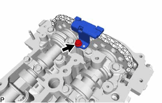
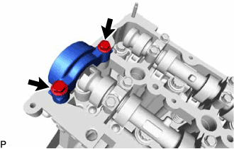
Text in Illustration *a Stopper Plate *b Pin Insert a pin into stopper plate hole of the No. 2 chain tensioner assembly and lock the No. 2 chain tensioner assembly.
-
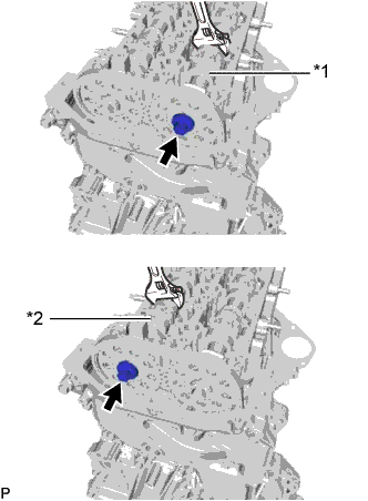
Text in Illustration *1 No. 1 Camshaft *2 No. 2 Camshaft Hold the hexagonal portion of the camshaft with a wrench and loosen the 2 bolts from the No. 1 camshaft and No. 2 camshaft.
CAUTION:
Be careful not to damage the cylinder head sub-assembly with the wrench.
-
Remove the 2 bolts and No. 3 camshaft bearing cap from the cylinder head sub-assembly.
-
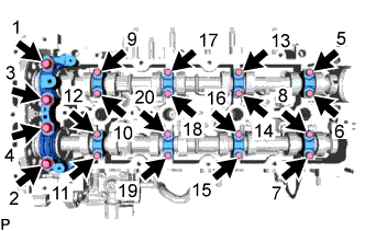
Using several steps, and remove the 20 bolt, No. 1 camshaft bearing cap and 8 No. 2 camshaft bearing caps from the cylinder head sub-assembly.
-
Raise the No. 1 camshaft and remove the bolt from the No. 1 camshaft.
-
Raise the No. 2 camshaft and remove the bolt from the No. 2 camshaft.
-
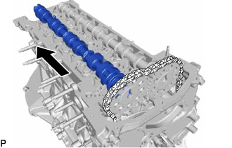
Remove the No. 2 camshaft from the camshaft timing sprocket.
-
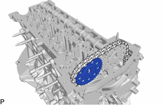
Remove the camshaft timing sprocket from the No. 2 chain sub-assembly.
-
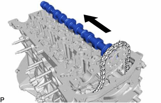
Remove the No. 1 camshaft from the camshaft timing sprocket.
-
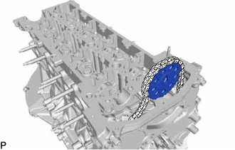
Remove the camshaft timing sprocket from the No. 2 chain sub-assembly.
-
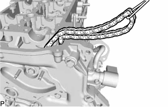
Suspend the No. 2 chain sub-assembly with a string or equivalent.
Tech Tips
Be careful not to drop the No. 2 chain sub-assembly inside the timing chain cover assembly.
-