ENGINE ASSEMBLY (w/ DPF) INSPECTION
-
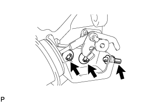
INSPECT SWIRL CONTROL VALVE ASSEMBLY
Note
Do not adjust the adjusting screw or 2 swirl control valve actuator installation bolts.
-
Check the operation of the swirl control valve.
-
Check that the valve is fully opened under normal conditions.
-
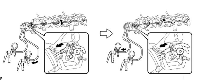
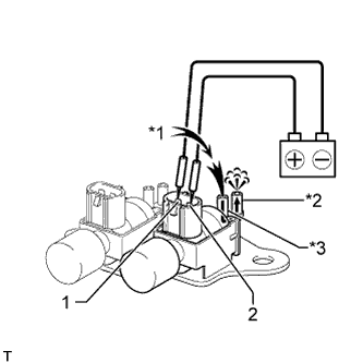
Connect the vacuum pumps as shown in the illustration. First apply negative pressure to the diaphragm closer to the intake manifold. This cause the actuator rod to move, which causes the swirl control valve to move. Then, apply negative pressure to the diaphragm on the outer side. This cause the actuator rod to move further, which also causes the swirl control valve to move further. Check that the valve is fully closed when a negative pressure of 35 kPa (263 mmHg, 10.3 in.Hg) is applied.
-
Wait for 1 minute and check that the vacuum pump needle does not move. If the result is not as specified, replace the intake manifold.
Tech Tips
When applying negative pressure to the diaphragm on the outer side, the diaphragm closer to the intake manifold must be in a vacuum state.
-
-
-
INSPECT NO. 1 VACUUM SWITCHING VALVE ASSEMBLY (for Swirl Control Valve)
-
Check the resistance of the vacuum switching valve.
-
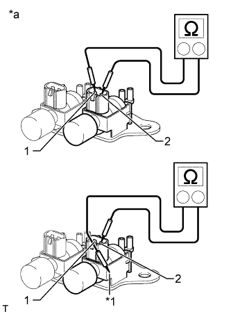
Text in Illustration *a Component without harness connected
(No. 1 vacuum switching valve)
*1 Body Measure the resistance according to the value(s) in the table below.
Standard Resistance Tester Connection Condition Specified Condition 1 - 2 20°C (68°F) 33 to 39 Ω 1 - Body ground Always 10 kΩ or higher 2 - Body ground If the result is not as specified, replace the No. 1 vacuum switching valve assembly.
-
-
Check the operation of the vacuum switching valve.
-
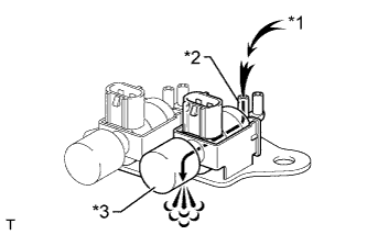
Text in Illustration *1 Air *2 Port E *3 Filter Check that air flows from port E to the filter.
If the result is not as specified, replace the No. 1 vacuum switching valve assembly.
-
-
Apply battery voltage across the terminals.
-
Text in Illustration *1 Air *2 Port F *3 Port E Check that air flows from port E to port F.
If the result is not as specified, replace the No. 1 vacuum switching valve assembly.
-
-
-
INSPECT NO. 2 VACUUM SWITCHING VALVE ASSEMBLY (for Swirl Control Valve)
-
Check the resistance of the vacuum switching valve.
-
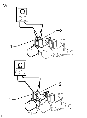
Text in Illustration *a Component without harness connected
(No. 2 vacuum switching valve)
*1 Body Measure the resistance according to the value(s) in the table below.
Standard Resistance Tester Connection Condition Specified Condition 1 - 2 20°C (68°F) 33 to 39 Ω 1 - Body ground Always 10 kΩ or higher 2 - Body ground If the result is not as specified, replace the No. 2 vacuum switching valve assembly.
-
-
Check the operation of the vacuum switching valve.
-
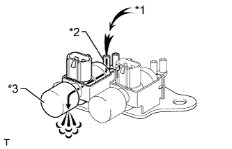
Text in Illustration *1 Air *2 Port E *3 Filter Check that air flows from port E to the filter.
If the result is not as specified, replace the No. 2 vacuum switching valve assembly.
-
-
Apply battery voltage across the terminals.
-
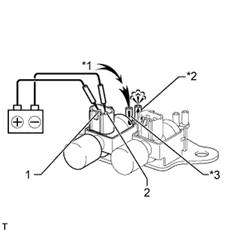
Text in Illustration *1 Air *2 Port F *3 Port E Check that air flows from port E to port F.
If the result is not as specified, replace the No. 2 vacuum switching valve assembly.
-
-