CYLINDER HEAD INSTALLATION

Note
-
When replacing the injectors (including shuffling the injectors between the cylinders), common rail or cylinder head, it is necessary to replace the injection pipes with new ones.
-
When replacing the fuel supply pump, common rail, cylinder block, cylinder head, cylinder head gasket or timing gear case, it is necessary to replace the fuel inlet pipe with a new one.
-
INSTALL CYLINDER HEAD GASKET
-
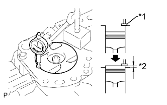
Text in Illustration *1 Measuring Tip *2 Protrusion Find where the piston head protrudes most by slowly turning the crankshaft clockwise and counterclockwise.
-
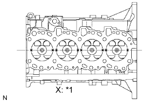
Text in Illustration *1 Measuring Point Measure the piston protrusion of each cylinder at 2 points as shown in the illustration.
-
For the piston protrusion value of each cylinder, use the average of the 2 measurements of that cylinder.
Standard piston protrusion 0.005 to 0.254 mm (0.0002 to 0.0100 in.) Tech Tips
If the protrusion is not as specified, remove the piston and connecting rod assembly and reinstall them.
-
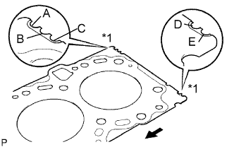
Text in Illustration *1 Cutout Mark 
Front Select a new cylinder head gasket.
Tech Tips
New cylinder head gaskets are available in 5 sizes, and are marked A, B, C, D or E.
New Installed Cylinder Head Gasket Thickness Item Specified Condition Mark A 0.80 to 0.90 mm (0.0315 to 0.0354 in.) Mark B 0.85 to 0.95 mm (0.0335 to 0.0374 in.) Mark C 0.90 to 1.00 mm (0.0354 to 0.0394 in.) Mark D 0.95 to 1.05 mm (0.0374 to 0.0413 in.) Mark E 1.00 to 1.10 mm (0.0394 to 0.0433 in.)
-
Select the largest piston protrusion value from the measurements made. Then select a new appropriate gasket according to the table below.
Gasket Size to be Used Gasket Size Piston Protrusion A 0.005 to 0.054 mm (0.0002 to 0.0021 in.) B 0.055 to 0.104 mm (0.0022 to 0.0041 in.) C 0.105 to 0.154 mm (0.0041 to 0.0061 in.) D 0.155 to 0.204 mm (0.0061 to 0.0080 in.) E 0.205 to 0.255 mm (0.0081 to 0.0100 in.)
-
-
Place the cylinder head on the cylinder block.
-
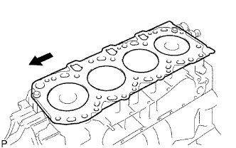
Place the cylinder head gasket on the cylinder block.
Text in Illustration Front Note
Make sure the gasket is installed in the correct direction.
-
Place the cylinder head on the cylinder head gasket.
-
-
-
INSTALL CYLINDER HEAD SUB-ASSEMBLY
Tech Tips
-
The cylinder head bolts are tightened in 3 progressive steps.
-
If any bolt is broken or deformed, replace it.
-
Apply a light coat of engine oil to the threads and under the heads of the cylinder head bolts.
-
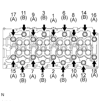
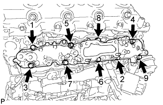
Install the 18 cylinder head bolts and 18 washers and tighten the bolts in several passes in the sequence shown in the illustration.
- Torque:
- 85 N*m { 867 kgf*cm, 63 ft.*lbf }
Standard Bolt Length Item Specified Condition A 110 mm (4.33 in.) B 167 mm (6.57 in.) If any of the cylinder head bolts does not meet the torque specification, replace it.
-
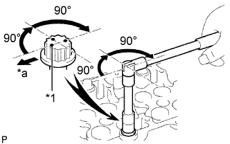
Text in Illustration *1 Paint Mark *a Front Mark the front of the cylinder head bolts with paint.
-
Further tighten the cylinder head bolts by 90° in the sequence shown in the illustration above.
-
Finally, tighten the cylinder head bolts by an additional 90°.
-
Check that the paint marks are now facing rearward.
-
-
INSTALL EXHAUST MANIFOLD
-
Set a new gasket on the cylinder head.
-
Install the exhaust manifold, 8 collars and 8 plate washers with 8 new nuts.
- Torque:
- 40 N*m { 408 kgf*cm, 30 ft.*lbf }
Note
Install the collars so that the side with the smaller external diameter faces the exhaust manifold.
-
-
INSTALL INTAKE MANIFOLD (w/o DPF)
-
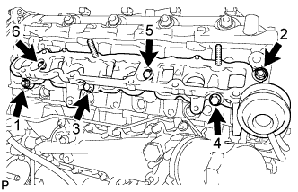
Temporarily install a new gasket and the intake manifold with the 4 bolts and 2 nuts.
-
Tighten the 4 bolts and 2 nuts in the order shown in the illustration.
- Torque:
- 29 N*m { 296 kgf*cm, 21 ft.*lbf }
Note
Make sure that the swirl control valve actuator is not damaged by the surrounding parts.
-
-
INSTALL SWIRL CONTROL VALVE ASSEMBLY (w/ DPF)
-
Temporarily install a new gasket and the swirl control valve with the 4 bolts and 2 nuts.
Note
Make sure that the swirl control valve actuator is not damaged by the surrounding parts.
-
Tighten the 4 bolts and 2 nuts in the order shown in the illustration.
- Torque:
- 29 N*m { 296 kgf*cm, 21 ft.*lbf }
-
-
INSTALL VACUUM SWITCHING VALVE SET (w/ DPF)
-
Install the vacuum control valve set with the 2 bolts.
- Torque:
- 20 N*m { 204 kgf*cm, 15 ft.*lbf }
-
Connect the 3 vacuum hoses and 2 connectors.
Tech Tips
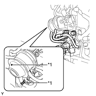
When connecting the hoses, match the color of the paint mark on the hoses to the color of the paint mark on the swirl control valve as shown in the illustration.
-
-
INSTALL INTAKE MANIFOLD (w/ DPF)
-
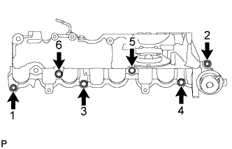
Temporarily install a new gasket and the intake manifold with the 7 bolts and 2 nuts.
-
Tighten the 7 bolts and 2 nuts in the order shown in the illustration.
- Torque:
- 20 N*m { 204 kgf*cm, 15 ft.*lbf }
-
Connect the vacuum hoses.
-
-
INSTALL NO. 1 INTAKE MANIFOLD INSULATOR (w/ DPF)
-
Install the No. 1 intake manifold insulator to the intake manifold.
-
-
INSTALL MANIFOLD STAY
-
Install the manifold stay with the 2 bolts.
- Torque:
- 19 N*m { 194 kgf*cm, 14 ft.*lbf }
-
-
INSTALL CYLINDER BLOCK INSULATOR
-
Install the cylinder block insulator to the cylinder head.
-
-
INSTALL NO. 1 COMPRESSOR MOUNTING BRACKET (w/ Air Conditioning System)
-
Temporarily install the No. 1 compressor mounting bracket with the 4 bolts.
-
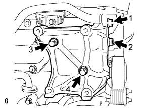
Tighten the 4 bolts in the order shown in the illustration.
- Torque:
- 45 N*m { 459 kgf*cm, 33 ft.*lbf }
Tech Tips
Make sure that the No. 1 compressor mounting bracket is in contact with the cylinder block.
-
-
INSTALL CAMSHAFT
-
INSTALL TIMING BELT
-
INSPECT AND ADJUST VALVE CLEARANCE
-
INSTALL TURBOCHARGER SUB-ASSEMBLY
-
INSTALL FRONT EXHAUST PIPE ASSEMBLY
-
w/ DPF: Click here
-
w/o DPF: Click here
-
-
INSTALL GLOW PLUG ASSEMBLY
-
w/ DPF: Click here
-
w/o DPF: Click here
-
-
INSTALL INJECTOR ASSEMBLY
-
w/ DPF: Click here
-
w/o DPF: Click here
-
-
INSTALL EGR COOLER ASSEMBLY
-
w/ DPF: Click here
-
w/o DPF: Click here
-
-
INSTALL COMMON RAIL ASSEMBLY
-
w/ DPF: Click here
-
w/o DPF: Click here
-
-
CHARGE REFRIGERANT (w/ Air Conditioning System)
-
Perform vacuum purging using a vacuum pump.
-
Charge with refrigerant HFC-134a (R134a).
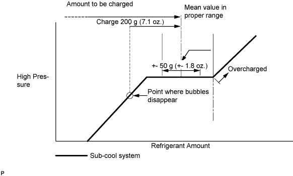
Standard Single A/C 520 to 580g (18.3 to 20.5 oz.) Dual A/C 670 to 730g (23.0 to 25.7 oz.) - SST
- 07110-58060 ( 07117-58090, 07117-78050, 07117-58070, 07117-58060, 07117-58080, 07117-88060, 07117-88070, 07117-88080 )
Note
-
Do not operate the cooler compressor before charging refrigerant as the cooler compressor does not work properly without any refrigerant, which causes the compressor to overheat.
-
Approximately 100 g (3.5 oz.) of refrigerant may need to be charged after bubbles disappear. The refrigerant amount should be checked by quantity, and not with the sight glass.
Tech Tips
Prepare a service can to recharge refrigerant if using the refrigerant gas collected with the freon collection/recycling device because the collective rate of the device is approximately 90%.
-
-
ADD ENGINE OIL
-
Add new engine oil.
Standard Oil Grade Item Oil Grade Oil Viscosity (SAE) w/ DPF ACEA C2
(Using engine oil other than ACEA C2 may damage catalytic converter)
- 0W-30
- 5W-30
w/o DPF G-DLD1, API CF-4, CF or ACEA B1
(You may also use API CE or CD)
- 5W-30
- 10W-30
- 15W-40
- 20W-50
Standard Capacity (w/ DPF) Item Fill Amount Drain and refill without oil filter change 6.6 liters (7.0 US qts, 5.8 Imp. qts) Drain and refill with oil filter change 6.8 liters (7.2 US qts, 6.0 Imp. qts) Dry fill 7.5 liters (7.9 US qts, 6.6 Imp. qts) Standard Capacity (w/o DPF) Item Fill Amount Drain and refill without oil filter change 6.8 liters (7.2 US qts, 6.0 Imp. qts) Drain and refill with oil filter change 7.0 liters (7.4 US qts, 6.2 Imp. qts) Dry fill 7.7 liters (8.1 US qts, 6.8 Imp. qts) -
Install the oil filler cap.
-
-
ADD ENGINE COOLANT
-
Firmly tighten the drain plugs.
-
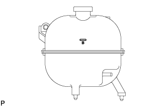
Fill the radiator reservoir assembly with engine coolant to the top of the inlet.
Standard Capacity Item Specified Condition w/o Heater 13.2 liters (13.9 US qts, 11.6 Imp. qts) w/ Front Heater 14.2 liters (15.0 US qts, 12.5 Imp. qts) w/ Front and Rear Heaters 16.2 liters (17.1 US qts, 14.3 Imp. qts) Note
Do not substitute plain water for engine coolant.
Tech Tips
-
Use of improper coolants may damage the engine cooling system.
-
Use only Toyota Super Long Life Coolant or similar high quality ethylene glycol based non-silicate, non-amine, non-nitrite, and non-borate coolant with long-life hybrid organic acid technology (coolant with long-life hybrid organic acid technology consists of a combination of low phosphates and organic acids).
-
-
Loosen the bleeder plug of the outlet housing.
-
When air is bled and the engine coolant drains out, firmly tighten the bleeder plug.
- Torque:
- 8.0 N*m { 82 kgf*cm, 71 in.*lbf }
-
Add engine coolant up to the B line mark in the radiator reservoir assembly and install the radiator reservoir cap sub-assembly.
-
Warm up the engine until the thermostat opens.
-
While the thermostat is open, circulate the engine coolant for several minutes.
Tech Tips
The thermostat open timing can be confirmed by pressing the No. 3 radiator hose by hand, and checking when the engine coolant starts to flow inside the hose.
-
-
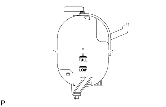
After the engine cools down, check that the engine coolant level is between the LOW and FULL level marks.
-
-
INSPECT FOR OIL LEAK
-
Start the engine. Make sure that there are no oil leaks from the areas that were worked on.
-
-
INSPECT FOR COOLANT LEAK
CAUTION:
Do not remove the radiator cap while the engine and radiator are still hot. Hot, pressurized engine coolant and steam may be released and cause serious burns.
-
Fill the radiator with coolant and attach a radiator cap tester to the radiator.
-
Warm up the engine.
-
Using a radiator cap tester, increase the pressure inside the radiator to 137 kPa (1.4 kgf/cm2, 19.9 psi), and check that the pressure does not drop.
Tech Tips
If the pressure drops, check the hoses, radiator and water pump for leaks. If no external leaks are found, check the heater core, cylinder block and cylinder head.
-
-
INSPECT FOR EXHAUST GAS LEAK
If gas is leaking, tighten the areas necessary to stop the leak. Replace damaged parts as necessary.
-
INSPECT FOR REFRIGERANT LEAK (w/ Air Conditioning System)
-
After recharging refrigerant gas, check for leakage of refrigerant gas using a halogen leak detector.
-
Carry out the test under the following conditions:
-
Stop the engine.
-
Secure good ventilation (the gas leak detector may react to volatile gases which are not refrigerant, such as evaporated gasoline and exhaust gas).
-
Repeat the test 2 or 3 times.
-
Make sure that there is some refrigerant remaining in the refrigeration system.
When the compressor is off: approx. 392 to 588 kPa (4 to 6 kgf/cm2, 57 to 85 psi)
-
-
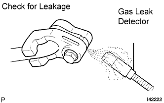
Using a gas leak detector, check for leakage of the refrigerant line.
-
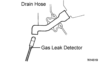
Bring the gas leak detector close to the drain hose with the detector's power off.
Tech Tips
-
After the blower motor has stopped, let the cooling unit stand for more than 15 minutes.
-
Bring the gas leak detector sensor under the drain hose.
-
When bringing the gas leak detector close to the drain hose, make sure that the gas leak detector does not react to volatile gases.
If such reaction is unavoidable, the vehicle must be lifted up.
-
-
If a gas leak is not detected on the drain hose, remove the blower motor control from the cooling unit. Insert the gas leak detector sensor into the unit and perform the test.
-
Disconnect the pressure switch connector and leave it for approximately 20 minutes. Bring the gas leak detector close to the pressure switch and perform the test.
-
-
INSPECT ENGINE OIL LEVEL
-
Warm up the engine, stop the engine and wait for 5 minutes.
-
Check that the oil level is between the upper level and lower level of the engine oil level dipstick.
If the oil level is low, check for leakage and add oil up to the upper level of the oil level dipstick.
-